


10
Connections
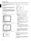
Pin assignment
RS-232C connector (D-sub 9-pin, female)
Pin No. Signal Operation Signal Direction
2 RXD Receive data VCR T Computer
3 TXD Send data VCR t Computer
7 RTS Request to send VCR t Computer
5 GND Singnal ground
RS-485 connector (RJ-11)
Pin No. A terminal signal B terminal signal
1 Not used Not used
2 Not used Not used
3 A signal B signal
4 B signal A signal
5 Not used Not used
6 Not used Not used
16
1
2
3
4
5
6
16
1
2
3
4
5
6
16
1
2
3
4
5
6
16
1
2
3
4
5
6
AB
RS-485
1 5
6
9
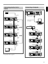
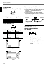
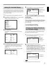
Make the connection to the RS-485 control terminal
using a modular cable (not supplied).
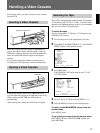
• If using a straight type cable, connect it between the
A terminals, or between the B terminals (see
illustration below).
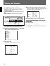
• If using a crossed type cable, connect it from the A
terminal to the B terminal, or from the B terminal to
the A terminal (see illustration below).
ADDRESS
RS-485/RS-232C selector
RS-485 TERMINATE switches
(DIP switches)
Switch No. Operation
1 - 7 Set address (1 is lowest bit and 7 is
highest) (ON:1, OFF:0)
7 is effective when using RS-485 connector
8 Not used
9 Select RS-485 or RS-232C
10 Terminate on/off when using RS-485
connector
Cross type
1 6
ADDRESS
10987654
ON
321
TERMINATERS-485
RS-232C
ON
OFF OFF
To terminal A
Straight-type cable
Cross-type cable
To terminal A
Straight type
not used
not used
not used
not used
not used
not used
not used
not used