Getting Started
SDA 601 Serial Digital Analyzer User Manual
5
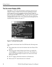
H With Pulse Cross enabled (see page 24), lets you “see” the con-
tents of the vertical and horizontal interval portions of the serial
video signal.
H Can include Cursor cross hairs for convenient positioning of the
Cursors (see page 22).
H When Highlighting (see page 23) is turned on, can help you locate
and identify errors in the picture, or the digital encoding of the
signal.
The AUX output signal may be thought of as “pseudo video.” It
is
derived from the serial input signal, converted to analog by an unfil-
tered 5-bit DAC. The signal can be the Y, R–Y, or B–Y component.
Please see page 35 for more information about the AUX output.
RS-232 Interface
Connect an ASCII, serial printer to the RS-232 connector to create
“hard copy” analysis reports, or to log errors detected during a Watch
session. See page 35 for the connector pinouts, and other necessary
communications settings. With a printer connected, you can
choose—through the Alarm menu—to have the SDA 601 log every
error as it occurs, or to print a Watch report every ten seconds. This
will permit unattended monitoring of your system. See page 20 for
more information.
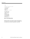
To test your printer connection and settings, perform a signal analysis
by pressing
Analyze. Then, press Shift-Analyze. The printer should re-
spond by printing an analysis report that resembles the one shown in
Figure 3.


