www.vxitech.com
SVM2608 Introduction 15
FIFO Mode
In FIFO mode, the user can retrieve data from the board as acquisition progresses. The memory
behaves as a FIFO: data is written into a circular buffer with new data overwriting older data
when the buffer is full. A Threshold Flag is available to monitor the status of the buffer and
prevent overwriting the data or under-reading it.
The Sample Points register that is used in Linear mode to determine the amount of data to be
captured is used in FIFO mode to determine the size associated with the FIFO Threshold Flag.
When the number of samples stored in memory equals the number of points set in the Sample
Points register, the FIFO Threshold flag is asserted. In this manner, the user can wait until a
certain number of samples are captured before they download data from the board. If the user
fails to retrieve the data from the card in time and new data overwrites older data, then the FIFO
Overrun flag is asserted. Conversely, if the user attempts to read more data than has been stored,
the FIFO Underrun flag is asserted. The FIFO Threshold flag is cleared when data is read from
the board and the total amount of “new (unread)” data in the buffer is less than the THRESHOLD
value. The FIFO Overrun and Underrun flags are cleared only when a new acquisition is
initiated.
Calibrations
Due to the nature of the semiconductors and passive components, not all parts have exactly the
same characteristics. Slight differences exist from component to component. While these
inconsistencies are unavoidable, they do not affect the basic functionality of the electronic
instrumentation. The precision of the instrument, however, can be altered by these variances.
One way to eliminate these slight variations is to use expensive, precision parts or to perform a
rigorous parts selection procedure to ensure consistency. These measures, however, would
dramatically increase the cost of the board. Another way to compensate for offset and gain
variations is to take a number of measurements using precision calibrated instruments of known
voltage and resistance. Their known values are then compared against the values attained for
each channel and the difference is used to adjust future measurements. These adjustments are
called calibrations. They are performed at the factory using approved calibration sources.
Test Bus
The SVM2608 is capable of performing a self-test to check for functionality and accuracy. Using
a local voltage reference source and local resistance references, basic function tests can be
performed. Four different voltage reference sources are available on the board: ±9.45 V and
±0.945 V. Two Resistance References are available: 128 Ω and 81.92 kΩ. Two different signal
generators can also be used for different tests: a RAMP generator and a PULSE generator. Any
of these locally generated test sources can be placed on the internal Test Bus (TB). The Test Bus
can then be connected to the input of any or all of the channels. Only one of the test signals can
be connected to the Test Bus at one time. The test sources can be connected to the Test Bus using
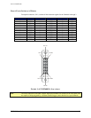
microprocessor commands. The Test Bus is also available to the user for monitoring on pins 24
and 13 of the Front Panel Connector. (See
Front Panel Interface Wiring for more detail.)
The self-test is performed by sending a command to the microprocessor, instructing it to run the
self-test (see
3Microprocessor Commands). When the microprocessor runs the self-test, a Test
Result is returned (see the description of the Self Test Command for a more detailed description).
Commands
The SVM2608 is equipped with a processor. While the processor is not directly involved in the
acquisition process, its presence on the board significantly enhances the capabilities of the
SVM2608 digitizer.
The user can choose to download the data on to a CPU and perform custom data processing, or
they can instruct the on-board microprocessor to perform one or several predefined calculations


