


www.vxitech.com
SVM2608 Introduction 19
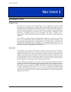
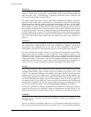
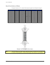
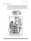
FRONT PANEL INTERFACE WIRING
Front-panel connector, J101, contains all the instrument signals for the Channels 0 through 3.
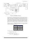
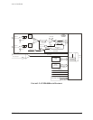
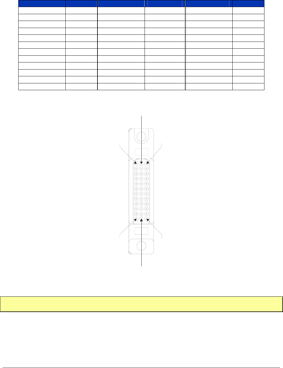
Pin 1
Pin 25
Pin 1
3
Pin 24
Pin 12
Pin 36
FIGURE 1-4: SVM2608 PIN LOCATIONS
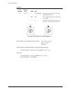
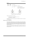
Note The SMA connectors associated with the high-speed channels are labeled on the front panel and
are capable of being triggered by a different external trigger source than the low-speed channels.
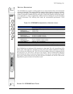
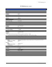
PIN NUMBER SIGNAL PIN NUMBER SIGNAL PIN NUMBER SIGNAL
1 GND 13 TB- 25 GND
2 CH1I- 14 GND 26 CH3I-
3 CH1- 15 GND 27 CH3-
4 CH1+ 16 GND 28 CH3+
5 CH1I+ 17 GND 29 CH3I+
6 GND 18 GND 30 GND
7 GND 19 EXTTRIGIN 31 GND
8 CH0I- 20 GND 32 CH2I-
9 CH0- 21 GND 33 CH2-
10 CH0+ 22 GND 34 CH2+
11 CH0I+ 23 GND 35 CH2I+
12 GND 24 TB+ 36 GND