VXI Technology, Inc.
34 SVM2608 Programming
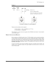
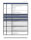
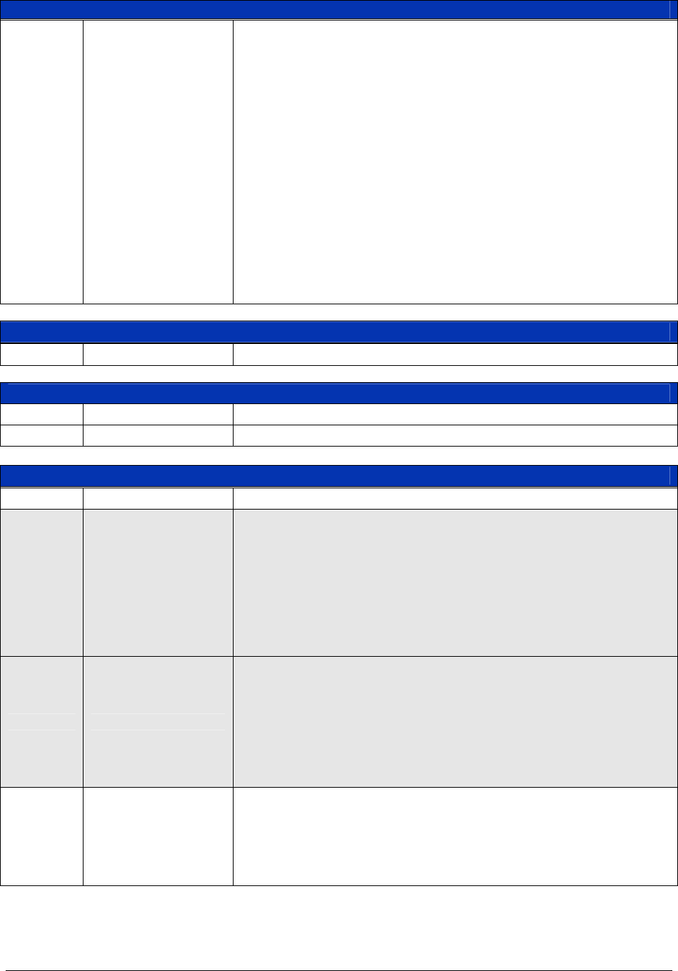
Force Trigger, Start Register (0x02) — Read & Write
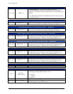
D5 – D0 START5 – 0
Acquisition Armed - These bits control whether or not the specified
channel is to be armed for an acquisition. A channel must remain
ARMED for the entire duration of the acquisition process. Clearing an
ARM bit will reset the internal state-machines and stop the acquisition.
One bit is assigned to each channel as follows:
D0 for Channel 0
D1 for Channel 1
D5 for Channel 5
Having one bit per channel allows multiple channels to be triggered
simultaneously.
0 = Channel not armed for acquisition
1 = Channel armed and ready for acquisition
P
on
state = 0
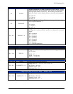
Reserved (0x04)
D15 – D0 Reserved These bits are reserved for future use.
External Trigger Level (0x06) — Read & Write
D15 – D12 Unused These bits are reserved for future use.
D11 – D0 External Trigger Level Sets the level at which the module triggers from an external source.
Control Register (0x08, 0x30, 0x58, 0x80, 0xA8, 0xD0) — Read & Write
D15 – D14 Unused These bits are reserved for future use.
D13 AC/DC Coupling
AC/DC Select - This bit selects between ac and dc coupling for high-
speed Channels 4 – 5.
0 = AC
1 = dc
P
on
state= 0
Note: This bit is only utilized by high-speed Channels 4 and 5. This bit is
unused for Channels 0 – 3.
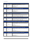
D12 1 MΩ/50 Ω
1 MΩ /50 Ohms - Selects between the 1 MΩ and 50 Ω
0 = 1 MΩ
1 = 50 Ω
P
on
state= 0
Note: This bit is only utilized by High-Speed Channels 4 and 5. This bit
is unused for Channels 0 – 3.
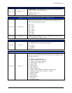
D11 TIMEOUTCTL
Timeout Control - This bit controls whether or not a timeout condition
will cause the timeout bit to be set in the interrupt status register.
0 = Disable timeout status bit
1 = Enable timeout status bit
P
on
state = 0


