www.vxitech.com
SVM2608 Programming 39
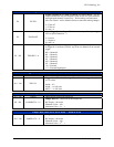
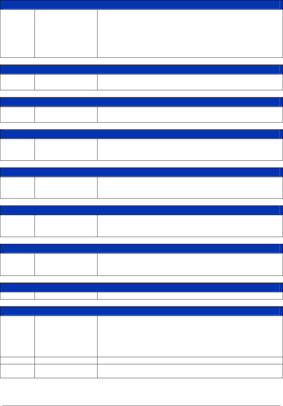
Command Register (0x22, 0x4A, 0x72, 0x9A, 0xC2, 0xEA) — Read and Write
D15 – D0 CMD15 – 0
Command Register - Writing to this register instructs the
microprocessor to perform the specified function. If this command
performs a calculation, the data is returned into the corresponding result
register.
For a detailed description of the commands, refer to the
23Microprocessor
Commands section.
FIFO Data (0x24, 0x4C, 0x74, 0x9C, 0xC4, 0xEC) — Read Only
D15 – D0 FIFODATA31 – 16
FIFO Data - Two registers are provided for retrieving FIFO data. This
allows for 32-bit transfer. One sample of data per 16-bit register.
FIFO Data (0x26, 0x4E, 0x76, 0x9E, 0xC6, 0xEE) — Read Only
D15 – D0 FIFODATA15 – 0
FIFO Data - Two registers are provided for retrieving FIFO data. This
allows for 32-bit transfer. One sample of data per 16-bit register.
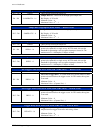
Results Register (0x28, 0x50, 0x78, 0xA0, 0xC8, 0xF0) — Read Only
D15 – D0 RESULT63 – 48
Result Data - When a process data command is issued to the
microprocessor, bits 63 through 48 of the 64-bit floating point result is
returned to this register. A status bit in the interrupt register is set.
Results Register (0x2A, 0x52, 0x7A, 0xA2, 0xCA, 0xF2) — Read Only
D15 – D0 RESULT47 – 32
Result Data - When a process data command is issued to the
microprocessor, bits 47 through 32 of the 64-bit floating point result is
returned to this register. A status bit in the interrupt register is set.
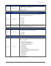
Results Register (0x2C, 0x54, 0x7C, 0xA4, 0xCB, 0xF4) — Read Only
D15 – D0 RESULT31 – 16
Result Data - When a process data command is issued to the
microprocessor, bits 31 through 16 of the 64-bit floating point result is
returned to this register. A status bit in the interrupt register is set.
Results Register (0x2E, 0x56, 0x7E, 0xA6, 0xCE, 0xF6) — Read Only
D15 – D0 RESULT15 – 0
Result Data - When a process data command is issued to the
microprocessor, bits 15 through 0 of the 64-bit floating point result is
returned to this register. A status bit in the interrupt register is set.
Reserved Registers (0xF8 – 0xFC)
D15 – D0 Unused This is reserved for future use.
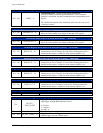
External Trigger Level - High-Speed Channels (0xFE) — Read & Write
D15
HS_EXT_
TRIG_SLOPE
High-Speed Input Trigger Source Slope – This bit sets the slope of the
input trigger for high-speed Channels 4 and 5.
0 = Positive
1 = Negative
P
on
state = 0
D14 – D12 Unused These bits are reserved for future use.
D11 – D 0 HS_EXT_TRIG 11 - 0
High-Speed External Trigger – Sets the level at which the high-speed
module triggers from an external source.


