


Cyclades-PR4000
Chapter 15 - IPX 139
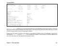
Enabling IPX
The first step is to activate the IPX feature in the router. This is accomplished using the menu option ADMIN
=>ENABLE FEATURES => IPX. The IPX protocol must also be activated in the menu CONFIG =>IPX => GENERAL.
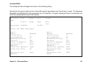
In this menu, the
Internal Network Number
(the unique number assigned to the router) and the
Maximum Number
of Hops
must be defined. The maximum number of hops defines how many routers can be on the path from this
router to the destination of any packet sent through this interface.
Configuring the Ethernet Interface
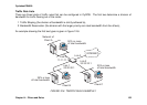
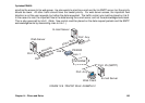
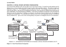
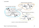
The example in Figure 13.1 will be used to explain the remaining parameters that must be configured. The
Ethernet interface for the PR2000 is examined first. In the menu CONFIG =>INTERFACE => ETHERNET =>
ENCAPSULATION, the Ethernet interface must be activated. The MAC address should be correct, as it is preset
at the factory. For IPX, the
Encapsulation
parameter should be set according to the value used by the servers on
the network..
In the menu CONFIG =>INTERFACE => ETHERNET => NETWORK PROTOCOL => IPX, the protocol should be
activated and the LAN Network Number (00A0B000 in the example) set. All other parameters are explained in
chapter 5.
Configuring Other Interfaces
This stage depends on which board is occupying slot 1 and which encapsulation will be used. Each encapsulation
option will be discussed separately. Read the chapter describing the configuration for the appropriate interface,
consulting this section for details on IPX-specific parameters.
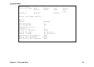
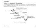
PPP
The parameters for the PPP data-link protocol are discussed in chapter 10. Only the parameters particular to the
IPX protocol will be described here. The are located in the CONFIG =>INTERFACE =><INTERFACE>
=>ENCAPSULATION =>PPP. The first parameter is the
IPXWAN Network Number
, shown in Figure 13.1 as
00B0C000.
IPX Compression
can be enabled, and if so the
Number of Compression Slots
determined. If enabled,
it must be used on both sides of the link (both routers in Figure 13.1) in order for the link to work.