3. Connections
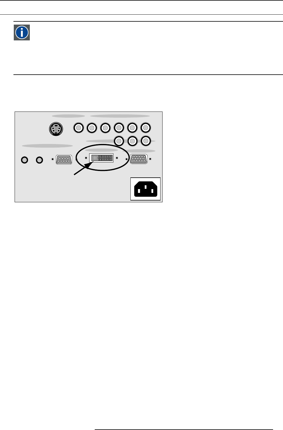
3.8 Digital Visual Interface (DVI) input
DVI
Digital Visual Interface is a display interface developed in response to the proliferation of digital flat panel displays.
The digital video connectivity standard that was developed by DDWG (Digital Display Work Group). This connection
standard offers two different connectors: one with 24 pins that handles digital video signals only, and one with 29 pins
that handles both digital and analog video. This standard uses TMDS (Transition Minimized Differential Signal) from
Silicon Image and DDC (Display Data Channel) from VESA (Video Electronics Standards Association).
DVI can be single or dual link.
Input specifications
Single link DVI
Differential input voltage: 200 mV - 800 mV
ASPECT
RATIO
12V TRIGGER
SCREEN
S-VIDEO VIDEO V
H
R/Pr
B/Pb
G/Y
Pr Pb Y
RS232/RS422
IN
CONTROL
DVI INPUT
VGA INPUT
COMPONENT
VIDEO INPUT RGB/COMPONENT INPUT
Image 3-8
DVI input
Pin assignment for the DVI connector.
Pin 1
TMDS DATA2-
Pin 13
TMDS DATA3+
Pin 2
TMDS DATA2+
Pin14 +5Power
Pin 3
TMDS DATA2/4 Shield
Pin 15
Ground (for +5V)
Pin 4
TMDS DATA4-
Pin 16 Hot Plug Detect
Pin 5
TMDS DATA4+
Pin 17
TMDS DATA0-
Pin 6
DDC Clock
Pin 18
TMDS DATA0+
Pin 7
DDC Data
Pin 19
TMDS DATA0/5 Shield
Pin 8 Not connected Pin 20
TMDS DATA5-
Pin 9
TMDS DATA1-
Pin 21
TMDS DATA5+
Pin 10
TMDS DATA1+
Pin 22
TMDS Clock Shield
Pin 11
TMDS DATA1/3 Shield
Pin 23
TMDS Clock+
Pin 12
TMDS DATA3-
Pin 24
TMDS Clock-
How to select the DVI Input ?
1. Press 3 on the RCU
Note: Another way of selecting the DVI input is entering the Main menu and selecting DVI.
R5976763 CINEVERSUM 60/70 22042004
21


