


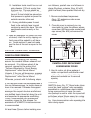
2. Install heavy-duty washer and socket
head cap screw, assembled as shown in
sketch titled "Cam Follower Replacement
E-Series Index Drives" in this Service
Manual. Use Red Perma-Lok
®
‚ and
torque the socket head cap screw to
specification. The tightening torque
depends on the size of the cam follower.
See the table titled "Torque Requirements
for Tightening Screws" in this Service
Manual for tightening torque.
3. Install bore plug.
4. Repeat steps to install all cam followers.
5. If a new cam is being installed, install all
but two (2) cam followers. See the sec-
tion titled "Cam and/or input Shaft
Replacement" in this Service Manual.
6. Re-install the socket head cap screws
and follower access cover, using "General
Electric Silicone Rubber RTV-6" or equiv-
alent as a sealant.
7. Re-install the socket head cap screws
and side access cover. This is an exter-
nal cover and sealant is not required.
9
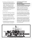
E-SERIES INPUT SHAFT AND CAM REMOVAL
CAM AND/OR INPUT SHAFT
REPLACEMENT:
INPUT SHAFT REMOVAL:
Instructions for removing the cam and input
shaft assume the follower wheel will not be
removed. If the follower wheel will be
removed, proceed to the section titled
"Follower Wheel and/or Output Bearing
Replacement" in this Service Manual.
Otherwise, proceed with the following steps.
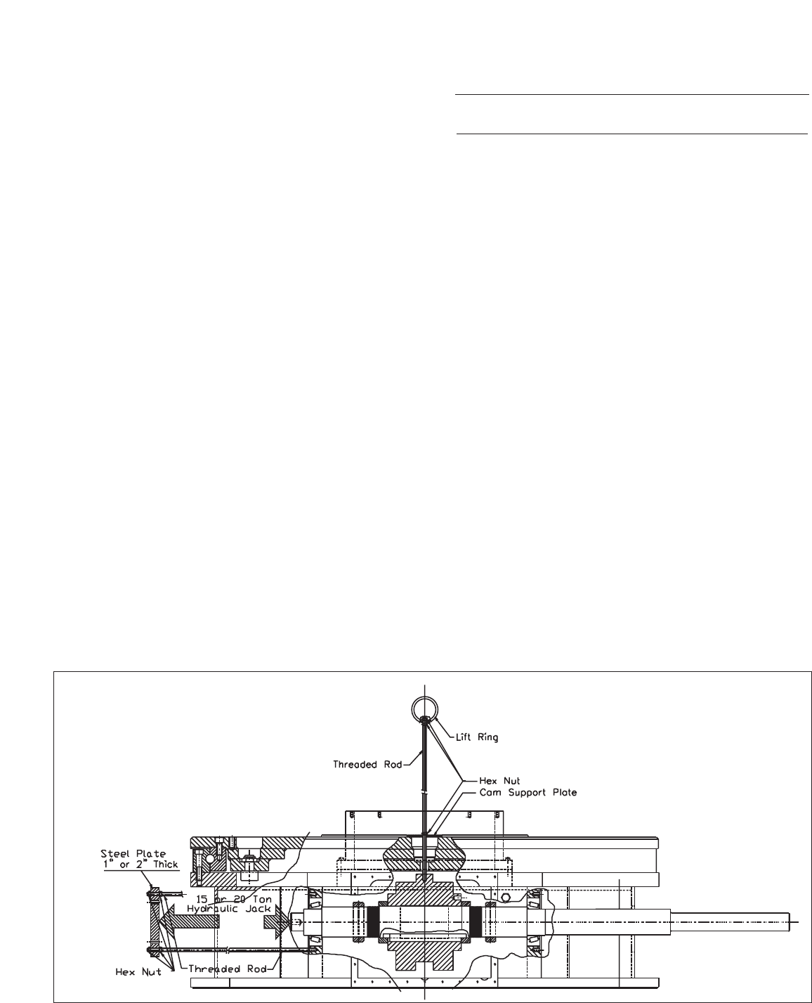
If the machine builder has provided access
holes to the cam follower screws, complete
removal of the support structure and fixtures
is not mandatory. The cam can be supported
during removal with a threaded rod through
one of the cam follower stud holes.
Otherwise, the support structure and fixtures
must be removed, or the support structure
and fixtures can be lifted two to three feet
above the unit and supported by appropriate
scaffolding. CAMCO recommends using pro-
fessional machinery riggers for this purpose.
The assistance of a CAMCO trained service-
man is recommended.