


CAM REMOVAL:
1. Once the input shaft has been removed,
use one of two methods to lower the cam
into the bottom of the housing.
1.1. Use a lift ring on the end of the treaded
rod and a boom crane to lift the cam
slightly, i. e. to relieve strain on the hex
nut. Then while using the lift ring to
support the cam, loosen the hex nut and
back it off several inches. Use the
boom crane to lower the cam into the
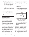
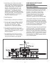
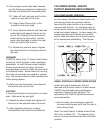
bottom of the housing. See sketch titled
"E-Series Input Shaft and Cam
Removal" in this Service Manual.
1.2. Or without using a lift ring (no access
for a boom crane), slowly loosen the hex
nut and lower the cam into the bottom of
the housing.
CAUTION
See "Approximate Weights" within this service
manual for sizing the lifting device. Make sure
the cam is supported.
2. Once the cam is sitting on the bottom of
the housing, remove the threaded rod, etc.
3. Use one of two methods to get the cam out
of the housing cavity.
3.1. Place a "Nylon Strap" through the bore
of the cam, and while pulling on the
strap, roll the cam out of the housing.
3.2. Alternatively, insert a piece of threaded
rod with a lift ring into the tapped hole in
the cam and using the lift ring, pull the
cam out of the housing cavity.
CAM INSTALLATION:
Instructions for replacing the cam assume the
follower wheel was not removed.
Before proceeding with installation of the new
cam, install all but two new cam followers.
Manually pull the follower wheel into a posi-
tion where one or more cam followers are
over the housing cavity. Use a come-a-long
or other device to pull the follower wheel and
any attached tooling into position. Two or
three cam followers can be accessed through
the large access opening in the housing. See
section titled "Cam Follower Replacement" in
this Service Manual.
Do not install the last two (2) cam followers
until the input shaft and cam have been
installed.
Once all but two (2) cam followers have been
replaced, place the cam inside the housing
cavity.
1. Before placing the cam inside the housing
cavity, check the input shaft diameter and
the cam bore size to ensure a slip fit.
1.1. The input shaft can be installed in the
cam and then removed to ensure a slip fit.
1.2. If the input shaft binds during installation,
hone the cam bore to provide a slip fit.
CAUTION
The cam must be a slip fit or slight press fit,
but the fit cannot be loose. Do not remove an
excessive amount of material.
2. The cam can be either rolled into the hous-
ing cavity, or it can be lifted and pushed
into the housing cavity. Use the best
method as determined by the situation.
3. Regardless of the method used to place the
cam in the housing cavity, placing the cam
into the housing cavity will be an awkward
process.
CAUTION
Make sure the cam is not damaged during this
process.
4. Install threaded rod and lift ring into the lift-
ing hole in the cam. Then lift the cam so
the input shaft can be pushed through the
cam.
13