


5.1.5. Put a hex nut on the threaded rod
and run it down until the nut is snug
against the plate and until the thread-
ed rod is supporting the weight of
the cam.
Note: The hole in the follower wheel and the
tapped hole in the cam do not line up exactly.
The threaded rod might be at a slight angle
until the bearing cartridges are removed. This
is acceptable, the threaded rod will straighten
out when the bearing cartridges are removed.
If threaded rod cannot be installed at this
time, place wooden blocks under the cam for
support and install threaded rod after remov-
ing the bearing cartridges.
5.2. Follower wheel was removed.
5.2.1. Install threaded rod into the "lift-
ing hole" in the cam and let the
threaded rod extend beyond the top
surface of the housing. Put a hex nut
on the threaded rod and run it down
until the nut is tight against the cam.
The length of the extension should be
sufficient to lower the cam into the
bottom of the housing.
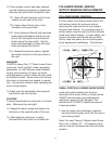
5.2.2. Place a piece of plate (approxi-
mately 3/4" x 6" x 36") with a hole
through the center over the threaded
rod. This plate sitting on the top
edge of the housing (or output bear-
ing) will act as a support during
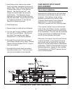
removal of the input shaft. See
sketch titled "E-Series Input Shaft
and Cam Removal" in this Service
Manual.
5.2.3. Put a hex nut on the threaded rod
and run it down until the nut is snug
against the plate and the threaded
rod is supporting the weight of the
cam.
6. Remove the reducer and any portion of the
drive package that would interfere with
removal of the input shaft.
7. Match mark the bearing cartridges.
Eccentric cartridges are used in E-Series
Index Drives to accommodate different cam
diameters. The cartridges must be
replaced in the same orientation as when
removed. Remove all socket head cap
screws (Item #24) securing the two (2)
bearing cartridges (Item #11) to the
housing (Item #1) and remove the bearing
cartridges.
7.1. This can be done by striking the car-
tridge with a soft faced hammer to break
any sealant and then prying the cartridge
away from the housing.
7.2. The input oil seal (Item #13) and input
bearing cup (Item #17) will stay with
each bearing cartridge when it is
removed. See sketch titled "E-Series
Input Shaft and Cam Removal" in this
Service Manual.
7.3. Make sure to note the color and num-
ber of any input shims (Item #12) at each
cartridge. The color and number of
shims used determines bearing preload.
8. Remove the input bearing cone (Item #17)
on the side of the input shaft with the
shortest extension.
8.1. The input bearing can be knocked off
with an aluminum bar from the inside of
the housing.
8.2. Alternatively a bearing puller can be
used to remove the bearing.
9. Completely remove the locknuts and lock-
washers on the side of the input shaft with
the shortest extension. Loosen the lock-
nuts and lockwashers on the other side of
the input shaft until they are completely off
the threaded portion of the input shaft.
10. Mount a puller to the housing on the side
of the input shaft with the shortest exten-
sion. Use the tapped holes in the housing
that were exposed when the bearing
11