


19
3. Thread lifting eyes into the threaded holes
in the bearing (two places 180 degrees
apart or three places 120 degrees apart)
and using a boom crane or hoist set the
bearing onto the housing.
4. Coat the dowel pin holes with anti-seize
lubricant and drive the dowel pins through
the bearing and into the housing.
5. Apply Red Perma-Lok‚ and install 16 to 40
socket head cap screws. Tighten to specifi-
cation. See "Metric Screw Tightening
Torques" in this Service Manual.
FOLLOWER WHEEL INSTALLATION:
Prior to installing the follower wheel proceed
as follows. Replace all cam followers in the
follower wheel. See the section titled "Cam
Follower Installation" in this Service Manual.
Install cam and input shaft if they were
removed. See the section titled "Cam and
Input Shaft Installation" in this Service
Manual. Clean and deburr all parts before
re-assembly. Follow tightening torque and
Perma-Lok
®
‚ recommendations as outlined
in this Service Manual and the "General
Service Manual".
1. Install follower wheel using the following
steps.
1.1. Use a boom crane or hoist to lower the
follower wheel into the pilot on the output
bearing.
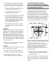
1.2. With the cam in place, be sure to posi-
tion the followers on either side of the
cam rib. The cam must be just entering
dwell and at the start of motion.
Note: For most Camco E-Series Index Drives
this is ten to fifteen (10˚ - 15˚) degrees clock-
wise or counter-clockwise from the mid-dwell
position. Refer to the model number of your
Index Drive for the amount of dwell provided.
Also refer to "Interpretation of Index Drive
Model Number" in the General Service
Manual.
1.3. If used, install pull type dowel pins.
Apply Red Perma-Lok.
1.4. Install 16 to 40 socket head cap
screws. Tighten to specification. See
table titled “Torque Requirements For
Tightening Screws” in this Service
Manual.
FINAL ASSEMBLY:
1. Reinstall the Large Access Cover.
1.1. Apply a thin bead of "General Electric
Silicone Rubber RTV-6" or equivalent to
the housing area where the cover seats.
2. Fill the index drive with recommended oil to
level indicated by the Sight Glass.
Lubricating oils should be high quality, well
refined petroleum oils or synthetic lubri-
cants with extreme pressure additives.
They may be subjected to high operating
temperatures, so they must have good
resistance to oxidation. These oils should
meet the American Gear Manufactures
Association (AGMA) standards, AGMA 4 EP
or AGMA 5 EP. Two such oils are:
Mobil's, Mobilgear 630, AGMA 5 EP
Mobil's, Mobil Synthetic oil SHC634,
AGMA 8 EP
See "General Service Manual" for compete
lubrication specifications.
A slightly high oil level will cause no
damage. Too low a level may result in unit
failure.
3. Lubricate the output bearing with grease.
Use grease that conforms to NGLI #2 or
NGLI #3. One such grease Is:
Mobil's Mobillith AW2
See "General Service Manual" for compete
lubrication specifications.
4. Adequate grease can be maintained in a
reused bearing by lubricating with four- (4)
oz. of grease. The bearing must be rotating
while lube (grease) is injected into