


INTRODUCTION
This service manual pertains to the disassembly and assembly of CAMCO’s Heavy Duty "E" Series Index Drive models
950E, 1150E, 1550E & 2050E.
This manual is to be used in conjunction with the General Service Manual, which describes the lubrication and general
maintenance of CAMCO Index Drives.
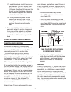
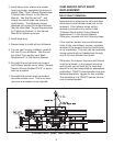
A cross section view of a typical CAMCO Heavy Duty "E" Series Index Drive model 950E, 1150E, 1550E or 2050E is
included in this manual. Item numbers within this Service Manual refer to the cross section view. Also included is a
generic Bill of Materials for your convenience in identifying and ordering spare or replacement parts. Always provide
the serial number from the Index Drive when ordering spare or replacement parts.
Some users of Index Drives have facilities and trained personnel to accomplish service repair. You must determine the
extent to which intricate servicing should be done by your own maintenance personnel. When in doubt, CAMCO rec-
ommends the assistance of a CAMCO trained serviceman when making repairs.
CAMCO suggests that it is best to completely remove all tooling from CAMCO's Heavy Duty "E" Series Index Drive
prior to completing repairs. Realistically, removing all tooling from CAMCO's Heavy Duty "E" Series Index Drive is pro-
hibitive. Tooling should be removed only as necessary in order to complete one or more of the following four related
procedures. The degree of disassembly increases with the addition of each procedure.
1. Input Oil Seal Replacement
Usually all tooling can be left in place when replacing oil seals. Removal of some portions of the drive package might
be required. See the section titled "Oil Seal Replacement" in this Service Manual for complete details.
2. Cam Follower Replacement
If the machine builder has provided access to the cam follower screws, the tooling does not need to be removed. Cam
followers can be replaced through the side access cover and follower access cover. See the section titled "Cam
Follower Replacement" in this Service Manual for complete details.
3. Input Shaft and/or Cam Replacement
In most cases, the input shaft and cam can be removed without removing all tooling. A section of the support struc-
ture and fixtures can be removed, or the support structure and fixtures can be lifted two to three feet above the unit
and supported by appropriate scaffolding. CAMCO recommends using professional machinery riggers for this pur-
pose. The assistance of a CAMCO trained serviceman is recommended. See the section titled "Input Shaft and/or
Cam Replacement " in this Service Manual for complete details.
Follower Wheel and/or Output Bearing Replacement
In most cases, the follower wheel and/or output bearing cannot be removed without removing the major portion of any
support structure and fixtures. An overhead hoist, boom crane or similar device must be used to lift the follower wheel
and output bearing. In some cases, the support structure and fixtures can be lifted two to three feet above the unit and
supported by appropriate scaffolding. The follower wheel and output bearing can then be removed with a boom crane
or similar device. CAMCO recommends using professional machinery riggers for this purpose. The assistance of a
CAMCO trained serviceman is recommended. See the section "Follower Wheel and/or Output Bearing Replacement"
is this Service Manual for complete details.
WARNINGS AND CAUTIONS:
Statements in this manual proceeded by the words WARNING or CAUTION and printed in italics are very important.
CAMCO recommends you take special notice of these during service or repair.
WARNING
Means there is the possibility of personal injury to yourself or others.
CAUTION
Means there is the possibility of damage to the CAMCO unit.
2