


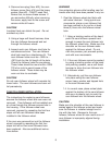
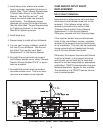
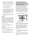

cartridges were removed. See sketch titled
"E-Series Input Shaft and Cam Removal" in
this Service Manual.
10.1. Using diametrically opposed tapped
holes, install two (2) threaded rods into
the tapped holes. These rods should
extend beyond the end of the input shaft
sufficiently to allow for a hydraulic jack.
10.2. Between the threaded rods mount a
2" square bar with clearance holes to
allow the threaded rod to pass through
the bar.
10.3. Use hex nuts and washers on both
sides of the 2" square bar to secure the
bar to the threaded rod.
10.4. Place a hydraulic jack between the
2" square bar and the end of the input
shaft. A 15 ton or 20 ton hydraulic jack
is suggested.
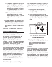
11. Mount wood blocks between the cam
and the housing to provide support (hold
cam in position) when pushing the input
shaft through and out of the cam.
11.1. On the side opposite the puller, the
side of the input shaft with the long shaft
extension, measure the distance
between the cam and the housing. Cut
wood blocks that sit on the bottom of
the housing and rest against the cam
and side of the housing to prevent the
cam from moving laterally, i.e. so a
hydraulic jack can be used to push out
the input shaft.
12. Using a hydraulic jack, push the input
shaft through the cam and out of the unit.
CAUTION
Support the input shaft as it is pushed out of
the cam. Use a boom crane or other means
for supporting the input shaft. See
"Approximate Weights" within this service
manual for sizing the lifting device. Make
sure the input shaft doesn’t fall when the end
is pushed out of the cam and becomes
unsupported.
13. Before proceeding, inspect the keyway in
the input shaft to make sure they are to
size. Also, inspect the oil seal diameters
for burrs, scratches, nicks or dings
13.1. An oversize keyway must be
remanufactured to proper specification.
13.2. Alternatively, the input shaft must be
replaced.
CAUTION
Loose fitting keys can cause premature failure
of the index drive.
14. Any imperfections must be removed from
the oil seal surface on the input shaft.
Otherwise, the oil seal will leak.
14.1. If an imperfections can not be
"polished" out, resurface the oil seal
diameter.
14.2. An alternative to resurfacing the oil
seal diameter is a wear sleeve. See the
section titled " Oil Seal Replacement" in
this Service Manual.
15. Prepare the input shaft for assembly by
removing the remaining locknuts and lock-
washer and bearing cone from the input
shaft.
16. Remove the bearing cups from the
bearing cartridges, and remove the used
oil seals from the bearing cartridges.
16.1. Measure the overall (stack) height of
the bearing cones and bearing cups.
16.2. Record these values with the previ-
ously recorded values for input shim.
12