


DISASSEMBLY AND INSPECTION:
DISASSEMBLY:
1. Remove only those structural members
and fixtures required to gain access to
the index drive and to allow for complet-
ing the necessary procedures.
2. Drain oil and flush with flushing solvent.
Retain any chips or broken pieces you
may find. These may aid in diagnosis.
2.1. Oil may be drained by removing
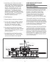
Magnetic Drain Plug (Item #23).
2.2. Alternatively, oil may be drained by
removing Cover (Item#7) and pumping
the oil from the unit's sump.
3. Remove socket head cap screws (Item #
27) and Cover (Item #6).
INSPECTION:
1. While slowly rotating input, inspect cam
(Item #4) surface to determine if cam must
be replaced. Inspect for a rough or rip-
pled surface, gouge marks, pitting and
other imperfections.
WARNING
CAMCO's Heavy Duty "E" Series Index Drives
cannot be "hand cranked" when completely
assembled, i.e. with follower wheel installed.
During some portions of repair, the motor
drive package is used to rotate the input shaft
and follower wheel. Some means for running
the motor at extremely low speeds is manda-
tory. Use extreme caution when operating the
motor during repairs.
2. Slowly index the unit and place the Index
Drive in a dwell position.
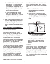
2.1. While manually applying torque to
the output follower wheel (Item #2),
check for pre-load in dwell. Try to
rotate the cam followers (Item #14)
that are in dwell.
2.2. Visually observe the surface of the
outer shell. Inspect followers for
damage or radial looseness.
Looseness should not exceed .001
inch. Do not confuse radial looseness
with axial endplay. End play will be
from .03 to .06 inch as a normal con-
dition. If endplay exceeds .06 inch
the followers should be replaced.
NOTE: Generally, cam followers are replaced
as added insurance against later failure.
When in doubt, replace the cam followers.
3. Broken cam followers indicate possible
damage to the follower wheel. Remove
any broken cam followers. See the sec-
tion titled "Cam Follower Replacement",
in this Service Manual. Inspect the cam
follower stud hole in the follower wheel
for damage, and to determine whether
the cam follower stud hole is "wallowed
out", elongated, oval, etc. Using the
nominal size of the cam follower stud as
a guide, verify a press fit between the
stud and the hole, -. 0005 to -. 0010 inch
for the full length of the hole.
4. Wobbling of the output or grinding noises
during each index indicate damage to
the output bearing (Item #5). Further
inspection requires removal of the follow-
er wheel. See the section titled
"Follower Wheel and Output Bearing
Replacement" in this Service Manual.
5. Replace cam followers if loose in dwell or
if the outer shell is visibly damaged. See
the section titled "Cam Follower
Replacement" in this Service Manual.
6. Replace the cam if imperfections are
noted. See the section titled "Cam
and/or Input Shaft Replacement" in this
Service Manual.
7. Replace the follower wheel if holes are
oversized. See the section titled
"Follower Wheel and Output Bearing
Replacement" in this Service Manual.
5