


18
Refer to the model number of your Index
Drive for the amount of dwell provided. Also
refer to "Interpretation of Index Drive Model
Number" in the General Service Manual.
WARNING
CAMCO’s Heavy Duty "E" Series Index Drives
cannot be "hand cranked" when completely
assembled, i.e. with follower wheel installed.
During some portions of repair, the motor
drive package is used to rotate the input shaft
and follower wheel. Some means for running
the motor at extremely low speeds is manda-
tory. Use extreme caution when operating the
motor during repairs.
2. Remove 16 to 40 socket head cap screws
(item # 28). CAMCO used Red Perma-
Lok
®
‚ when tightening these screws and it
may require heating the screw for ease of
removal.
CAUTION
Do not overheat. Overheating can distort
mating parts.
Note: Some E-Series Index Drives may have
pull type dowel pins installed between the fol-
lower wheel and output bearing. This is not
standard practice. If dowel pins were
installed, use a Slide Hammer and remove
these dowel pins.
3. Thread lifting eyes into the tapped holes in
the output face of the follower wheel. (Two
places 180 degrees apart or three places
120 degrees apart).
4. Using a boom crane or hoist, lift up the fol-
lower wheel. The follower wheel should
break free at this point and permit it to be
lifted clear. If binding occurs between the
output wheel and the locating pilot, break
free by tapping the follower wheel with a
soft faced hammer, alternating from side
to side.
CAUTION
See "Approximate Weights" within this Service
Manual for sizing the lift device.
OUTPUT BEARING REMOVAL:
1. If the output bearing (Item #2) is to be
replaced, remove the 16 to 40 socket head
cap screws (Item #30) fastening the output
bearing (Item #6) to the housing. CAMCO
used Red Perma-Lok‚ when tightening these
screws and it may require heating the screw
for ease of removal.
CAUTION
Do not overheat. Overheating can distort
mating parts.
2. From the underside of the housing flange,
drive the dowel pins (Item # 31) upward and
out of the bearing.
3. Thread lifting eyes into the tapped holes in
the top face of the output bearing. (two
places 180 degrees apart or three places
120 degrees apart).
4. Using a boom crane or hoist, lift up the
output bearing. The output bearing should
break free at this point and permit lifting it
clear. If binding occurs, break the output
bearing free by tapping the bearing with a
soft faced hammer, alternating from side to
side.
CAUTION
See "Approximate Weights" within this Service
Manual for sizing the lift device.
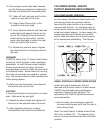
OUTPUT BEARING INSTALLATION:
1. Install the output bearing using the follow-
ing steps.
2. Apply a bead of "General Electric Silicone
Rubber RTV-6" on top of the housing in the
area of bearing contact.