


dCS 954 User Manual Manual for Standard Software Version 1.5x
dCS Ltd June 2000
Manual part no: DOC136954 iss 2B1
Page 10
file 135954ma2b1.pdf available from website
Contact
dCS
on + 44 1799 531 999 email to: more@dcsltd.co.uk
(inside the UK replace + 44 with 0) web site: www.dcsltd.co.uk
T
HE
H
ARDWARE
– C
ONTROLS AND
C
ONNECTORS
Rear Panel
PUSH PUSH PUSH PUSH PUSH
Analogue
CH1(L) CH2(R) Sensitivity
CH1(L) CH2(R)
Digital I/O
Reference In Reference Out AES1 AES2 AES3 AES4 CH1 CH2
In Out
SDIF-2/DSD
75R
Clk
Remote
In
Out
MAINS FUSE 2A(T) ON OFF
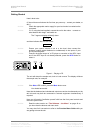
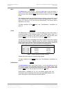
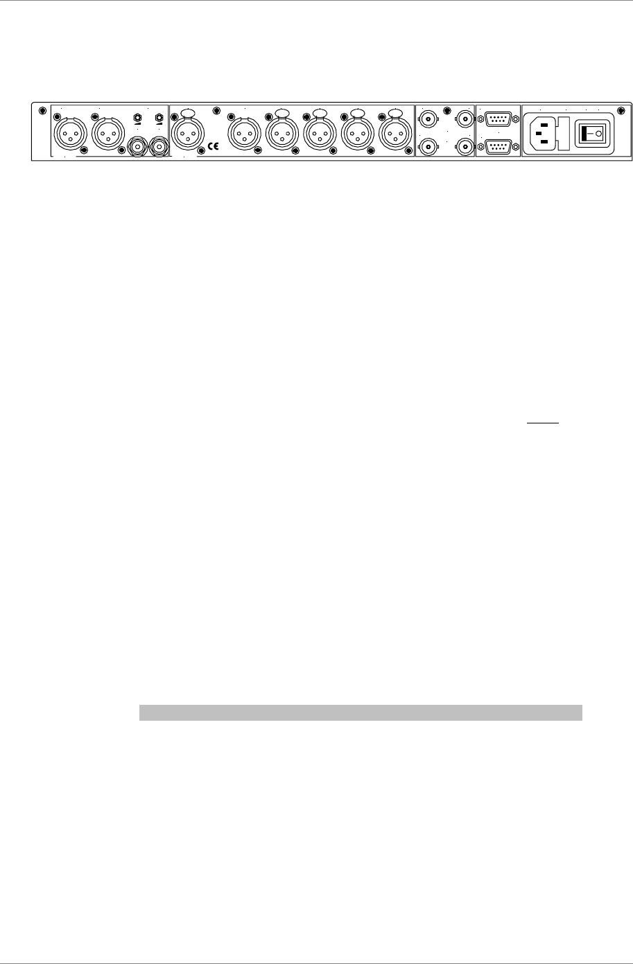
Figure 2 – Rear Panel
All input and output connectors are mounted on the rear panel. Individual
connectors are clearly identified by the panel legend. Viewed from the rear from
left to right, the connectors are as follows:
Balanced Analogue Outputs 3 pin XLR male (2 off)
Unbalanced Analogue Outputs RCA phono (2 off)
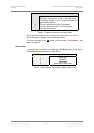
Output Level Adjustment (trimmers)
Two multi-turn potentiometers set the full scale output levels for the Balanced
Outputs only. These are factory preset for full scale with output levels of
+14dBu. If necessary, adjust with a suitable trim tool or a small flat-bladed
screwdriver. Turn clockwise for increased gain. Take care to ensure the stereo
outputs remain in balance. The trim range is ±6dB.
Reference In 3 pin XLR female
Reference Out 3 pin XLR male
Reference In is an AES/EBU reference input for synchronising the unit to a
Master Clock. Reference Out is an unbuffered loop through, directly coupled to
it, for use in a reference daisy chain. A terminating resistor may be turned on or
off, using the menu (see Ref In command, page 23), if several units are to be
daisy chained with the same word clock.
AES1, 2, 3 & 4 Digital Inputs 3 pin XLR female (4 off)
Four AES/EBU inputs which may be used independently or in groups of two
(Dual AES on AES1 & 2 or on AES3 & 4) or four (Quad AES or 4-wire DSD).
P3D units will also accept DSD in P3D format connected to AES1, 2 & 3.
SDIF/DSD CH1, CH2 Data BNC (2 off)
These BNC connectors can be both inputs and outputs. In normal operation
they are inputs for SDIF-2 encoded PCM, or SDIF-2 or SDIF-3 encoded DSD.
They are both TTL level signals for a 75 ohm line. They can be set to accept
TTL level AES3 coded signals, using the menu (see BNC I menu command,
page 26).
In addition, they can be used as data outputs, for re-formatting DSD data, in
DDC mode. See the Ref In menu command on page 23.