


dCS 954 User Manual Manual for Standard Software Version 1.5x
dCS Ltd June 2000
Manual part no: DOC136954 iss 2B1
Page 23
file 135954ma2b1.pdf available from website
Contact
dCS
on + 44 1799 531 999 email to: more@dcsltd.co.uk
(inside the UK replace + 44 with 0) web site: www.dcsltd.co.uk
If the input format is set to Single, Dual or Quad AES format, the unit will ignore
the message flags and group the AES inputs accordingly.
Set A-Sel to Off to disable automatic input selection.
RS232 -
Displays - and allows access to – the unit’s RS-232 identity code (an address
between 0 and 99). This is used by the remote control software to send specific
messages to specific units. Use
Up and Down to change this address if you are
operating several units in a multichannel set up. The RS-232 control formats
and procedures are covered in more detail in section “RS-232 Remote Control
Interface” starting on page 56
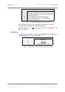
IMPORTANT!
When using the Remote Control, each unit in the daisy chain MUST be set to
a different RS-232 address.
Ref In -
Displays and sets the mode of the AES Reference In/Out connectors. The
options are:
Route Reference Out (connected in parallel with
Reference In – beware!) is internally driven with
the selected AES input signal.
If the input is Dual or Quad AES, the data on the
lowest of AES1 or AES3 appears on Reference
Out.
If BNC is selected, there is no output.
Loop The unit attempts to lock to Reference In, which is
looped through to the Reference Out, with no
termination resistor (termination is then about 1kΩ,
so several units can be daisy chained).
Loop.t As above, but terminates the input to achieve
110Ω. Use at the end of a daisy chain.
ddC Converts the data on the selected input to single
AES and sends it to Reference Out.
The data on a Single AES input is copied with no
conversion.
The data on a Dual or Quad AES input is converted
to Double speed Single AES. 176.4kS/s is
converted to 88.2kS/s and 192kS/s is converted to
96kS/s.
If BNC in SDIF mode is selected, the output is AES
clock with no data at the Word Clock rate.
If the input is 4-wire DSD, the data is converted to
SDIF format DSD and sent to the SDIF inputs.
SDIF Ch1 is checked first before the SDIF inputs
are changed to DSD outputs.
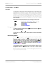
IMPORTANT!
In DDC mode, the analogue outputs are generally muted because the units
resources are used to perform a digital to digital conversion. They are not
muted if the input is 4-wire DSD.