


dCS 954 User Manual Manual for Standard Software Version 1.5x
dCS Ltd June 2000
Manual part no: DOC136954 iss 2B1
Page 59
file 135954ma2b1.pdf available from website
Contact
dCS
on + 44 1799 531 999 email to: more@dcsltd.co.uk
(inside the UK replace + 44 with 0) web site: www.dcsltd.co.uk
Command Streams -
Example – a system of 9 units with ID’s set up as noted:
1 Master Clock (ID 1),
4 P3D compatible ADCs (ID 2, 3, 4 and 5),
4 P3D compatible DACs (ID 6, 7, 8 and 9).
RS232 operating at 1200 baud.
It is assumed that the transmitter operates on a round robin polling scheme and
that each step completes before the next allowing for time outs. Except in the
case of a time out a unit should not be accessed within the response time of its
previous command. Within each step there is no need to wait for the command
response time prior to moving on to the next unit – once an acknowledge has
been received, the controller can safely assume that the unit is getting on with
the command it has received, and can move on to the next unit. At the end of a
step there is no need to wait before moving on to the next step.
Command strings are not given fully, the parameter string and the checksum
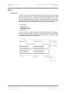
are not explicitly given. A typical command is shown as:
[ID][Command Type], information about command
A typical response is:
[ACK Type][ID], information (when requested)
When changing the operating frequency of a unit the internal crystals are
switched. It is recommended that after a crystal switch units are allowed to
settle for a short time (< 1 second) to ensure optimum performance. In this
case the units are being controlled by a Master Clock, so time should be allowed
for this to switch and for the other units connected to it to also switch and begin
to settle. It is recommended that there is no RS-232 activity for 3 seconds after
the Master Clock frequency is switched to ensure all units have time to settle.
When operating in DSD mode units assume their reference clocks are operating
at 44.1kHz. If a different frequency reference is used they will continuously
monitor the reference clock frequency, preventing RS-232 accesses. It is
therefore important to ensure the reference clock is set to 44.1kHz prior to
entering DSD mode, and that DSD mode is left prior to changing the reference
clock to another frequency.
Example: Switching to 96k PCM -
The following example covers the system of nine units, in two complex format
changes. Change the ADC and DAC operating mode to PCM prior to changing
the Master Clock frequency. Change the DAC operating mode prior to the ADC.
When changing the Master Clock frequency the system should be allowed to
settle to the new frequency before any further RS-232 activity.
1) Command DACs 6, 7, 8 and 9 to change mode, the units may take up to
15 seconds to complete this command (if the previous mode had been
DSD the FPGAs need to be re-loaded, which takes time). There is no
need to wait prior to moving on to step 2.
Transmit -> [6][DSD_MODE], to change mode to PCM of unit 6
Responds -> [ACK 15 seconds][6], requested mode
Transmit -> [7][DSD_MODE], to change mode to PCM of unit 7