


dCS 954 User Manual Manual for Standard Software Version 1.5x
dCS Ltd June 2000
Manual part no: DOC136954 iss 2B1
Page 33
file 135954ma2b1.pdf available from website
Contact
dCS
on + 44 1799 531 999 email to: more@dcsltd.co.uk
(inside the UK replace + 44 with 0) web site: www.dcsltd.co.uk
Replaying 6 channel DSD from a 24 track 16/44.1 PCM Recorder
PUSH PUSH PUSH PUSH PUSH
Analogue
CH1(L) CH2(R) Sensitivity
CH1(L) CH2(R)
Digital I/O
Reference In Reference Out AES1 AES2 AES3 AES4 CH1 CH2
In Out
SDIF-2/DSD
75R
Clk
Remote
In
Out
MAINS FUSE 2A(T) ON OFF
Balanced
outputs
Unbalanced
outputs
- or -
To pre or power amplifier
dC S 954
Ch5 Ch6
PUSH PUSH PUSH PUSH PUSH
Analogue
CH1(L) CH2(R) Sensitivity
CH1(L) CH2(R)
Digital I/O
Reference In Reference Out AES1 AES2 AES3 AES4 CH1 CH2
In Out
SDIF-2/DSD
75R
Clk
Remote
In
Out
MAINS FUSE 2A(T) ON OFF
From 24 channel 44.1kS/s 16 bit recorder
Balanced
outputs
Unbalanced
outputs
- or -
To pre or power amplifier
dC S 954
Ch3 Ch4
PUSH PUSH PUSH PUSH PUSH
Analogue
CH1(L) CH2(R) Sensitivity
CH1(L) CH2(R)
Digital I/O
Reference In Reference Out AES1 AES2 AES3 AES4 CH1 CH2
In Out
SDIF-2/DSD
75R
Clk
Remote
In
Out
MAINS FUSE 2A(T) ON OFF
Balanced
outputs
Unbalanced
outputs
- or -
To pre or power amplifier
dC S 954
Ch1 Ch2
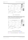
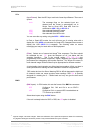
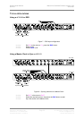
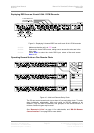
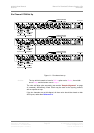
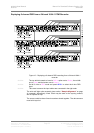
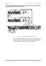
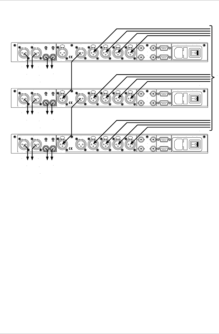
Figure 12 – Replaying a 6 channel DSD recording from a 24 track 16/44.1
recorder
do this: The top dCS 954 needs to have its Ref In option set to Route, the middle
one to Loop and the bottom one to Loop.t.
do this: Set all 3 units to DSD mode and press AES 1 to select the 4-wire DSD
input.
do this: Take care to ensure the input cables are connected in the right order.
The units self align quite accurately (see section “Sample Alignment” on page
41 onwards). Alternatively, Word Clock may be used as the syncing method,
with no special set ups.
The source could be three 8-track recorders slaved together. The data streams
must be bit-sync’ed.