


About Your System 13
Back-Panel Features and Indicators
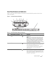
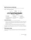
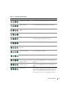
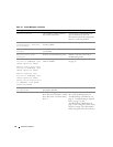
Figure 1-2 shows the controls, indicators, and connectors located on the system's back panel.
Figure 1-2. Back-Panel Features and Indicators
Connecting External Devices
When connecting external devices to your system, follow these guidelines:
• Most devices must be connected to a specific connector and device drivers must be installed before the
device operates properly. (Device drivers are normally included with your operating system software or
with the device itself.) See the documentation that accompanied the device for specific installation
and configuration instructions.
• Always attach external devices while your system is turned off. Next, turn on any external devices
before turning on the system (unless the documentation for the device specifies otherwise).
For information about individual connectors, see "Jumpers and Connectors" on page 89. For information
about enabling, disabling, and configuring I/O ports and connectors, see "Using the System Setup Program"
on page 23.
Power Indicator Codes
The power button on the front panel controls the power input to the system's power supply. The power
indicator can provide information on power status (see
Figure 1-1
). Table 1-3 lists the power button
indicator codes.
1 serial connector 2 video connector 3 expansion slot
4 NIC1 connector 5 NIC2 connector 6 power connector
7 power cable retention bracket 8 system identification button 9 system status indicator
10 system status indicator LED
cable connector
11 USB connector 12 USB connector
721345 6
10 9
11
12
8