


36 Installing System Components
Inside the System
CAUTION: Only trained service technicians are authorized to remove the system cover and access any of the
components inside the system. See your Product Information Guide for complete information about safety
precautions, working inside the computer, and protecting against electrostatic discharge.
CAUTION: The memory modules can become extremely hot during normal operation. Allow the modules
sufficient time to cool before handling.
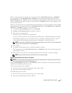
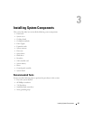
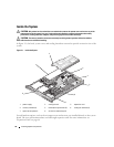
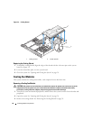
In Figure 3-1, the bezel, system cover, and cooling shroud are removed to provide an interior view of the
system.
Figure 3-1. Inside the System
Several hardware options, such as the microprocessors and memory, are installed directly on the system
board. The riser card accommodates one half-length expansion card. For more information, see
"Expansion Cards" on page 44.
7
4
3
5
2
1
6
8
1 power supply 2 cooling shroud 3 expansion card
4 memory modules (8) 5 heatsink/microprocessor (2) 6 cooling fan modules (2)
7 optical drive (optional) 8 3.5-inch hard drive bays (2)