• Maintain a back pressure on the system sufficient to prevent gas break out.
• Maintain flow velocity at the sensor within the specified limits.
1.4.4 Solids measurement considerations
Consider the following to avoid issues related to solids contamination:
• Avoid sudden changes of the fluid velocity that may cause sedimentation.
• Install the meter far enough downstream from any pipework configuration that may
cause centrifuging of solids (such as at a pipe bend).
• Maintain flow velocity at the meter installation that is within the specified limits.
• Use filtration in your process, if necessary.
1.4.5 Thermal effects considerations
For high viscosity fluids, you should minimize any temperature gradients in the fluid, and
in the piping and fittings immediately upstream and downstream of the meter. Minimizing
temperature gradients reduces the effect of viscosity changes. We recommend the
following to reduce the thermal effects to your meter installation:
• Always insulate the meter and surrounding pipework thoroughly.
- Insulation must be at least 1 inch (25 mm) of rockwool, preferably 2 inches (50
mm), or use an equivalent insulating heat jacket.
- Insulation must be enclosed in a sealed protective casing to prevent moisture
ingress, air circulation, and crushing of the insulation.
- For flow-through chamber installations, Micro Motion provides a special
insulation jacket because of the opportunity for low volumetric flow rates
(hence, low heat flow) and increased vulnerability to temperature effects.
• Avoid direct heating or cooling of the meter and associated pipe work upstream and
downstream that is likely to create temperature gradients.
• If it is necessary to provide protection against cooling because of loss of flow, you
can apply electrical trace heating. This type of heating must be thermostatically
controlled, and the thermostat must be set to operate below the minimum
operating temperature of the system.
1.5 Recommended installations for short-stem
meters
Micro Motion recommends three standard installations for the short-stem meter to
alleviate any need for onsite calibration. All meters are factory calibrated for these types of
installations and take into consideration the potential boundary effect of each installation.
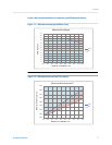
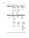
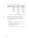
Table 1-1 highlights these different installations according to specific conditions or
requirements that may exist for your process environment.
Planning
Installation Manual 7


