


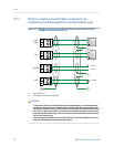


3.5.1 Wire to a signal converter/flow computer in an
explosion-proof/flameproof or non-hazardous area
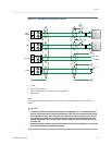
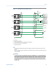
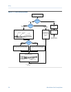
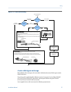
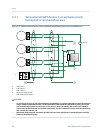
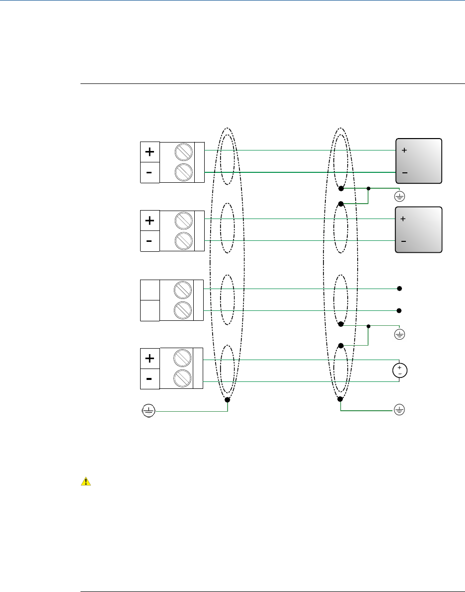
Wiring to a signal converter/flow computer in an explosion-proof/
flameproof or non-hazardous area
Figure 3-7:
mA1+
HART
RS-485
PWR
TPS
AA
B
24 VDC
RS-485 A
RS-485 B
A
B
A. Active HART host
B. Active signal converter/flow computer
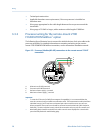
CAUTION!
• To meet the EC Directive for EMC (Electromagnetic Compatibility), it is recommended that
the meter be connected using a suitable instrumentation cable. The instrumentation cable
should have individual screen(s), foil or braid over each twisted pair and an overall screen to
cover all cores. Where permissible, the overall screen should be connected to earth at both
ends (360° bonded at both ends). The inner individual screen(s) should be connected at only
one end, the controller end.
• Metal cable glands should be used where the cables enter the meter amplifier box. Unused
cable ports should be fitted with metal blanking plugs.
Wiring
42 Micro Motion Fork Viscosity Meter