


Note
- Flow velocity at the pipe wall and fluid viscosity must be within the limits shown to ensure
that the fluid within the pocket is refreshed in a timely manner. This installation will not
respond as rapidly as the free-stream installation to step changes in viscosity.
- The thermal mass of the flanges may affect the response time of the meter to
temperature changes.
• Attach the PFA ring and circlip to the underside of the meter flange before installing
the meter in your application (see Section 2.7).
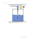
Procedure
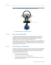
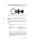
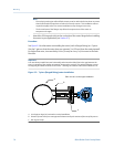
See Figure 2-3 for information on installing the meter (with a flanged fitting) in a T-piece.
Size the T-piece so that the meter tines are retracted 1 in (25 mm) from the main pipe wall.
For higher flow rates, increase this by 0.4 in (10 mm) for every 1 m/s increase in the main
flow rate.
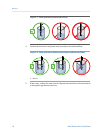
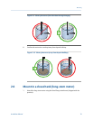
Important
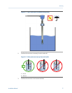
You must always install the meter horizontally and oriented to allow flow in the gap between the
tines, irrespective of the pipeline orientation (horizontal or vertical). This position helps to prevent
the trapping of bubbles or solids on the meter – allowing the solids to sink and the bubbles to rise.
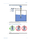
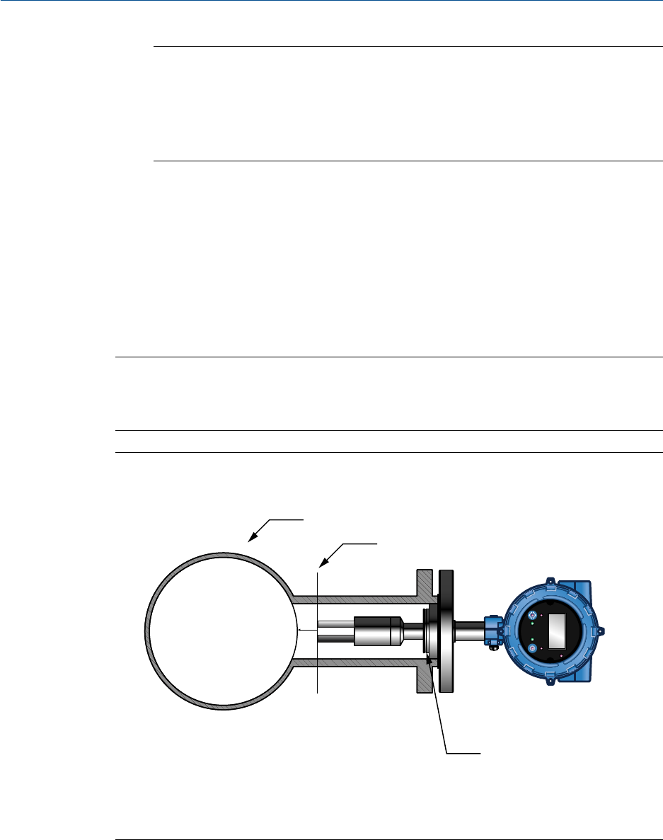
T-piece (flanged fitting) meter installationFigure 2-3:
STATUS
SCROLL SELECT
B
A
C
Plan view of a vertical pipe installation
A. 4-inch pipe or larger for horizontal or vertical installations
B. Distance of meter tines from main pipe wall is determined by the maximum flow rate of the process.
C. PFA ring and circlip
Mounting
14 Micro Motion Fork Viscosity Meter