


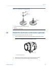
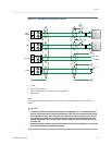
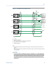
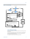
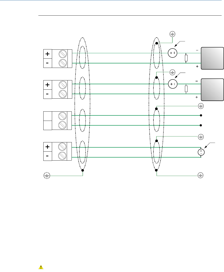
Wiring the Discrete output versionFigure 3-2:
mA1+
HART
RS-485
PWR
DO
AA
B
RS-485 A
RS-485 B
C
E
D
B
A
A
A
A. 24 VDC
B. R
load
(250 Ω resistance)
C. HART-compatible host or controller; and/or signal device
D. R
load
(500
Ω
resistance recommended)
E. Discrete input device
Note
• For operating the milliamp output with a 24V supply, a maximum total loop resistance of 657
Ω
is
allowed.
• When operating the Discrete output with a 24 VDC power supply, a maximum total loop resistance of
1300
Ω
is allowed.
CAUTION!
• To meet the EC Directive for EMC (Electromagnetic Compatibility), it is recommended that the
meter be connected using a suitable instrumentation cable. The instrumentation cable should
have individual screen(s), foil or braid over each twisted pair and an overall screen to cover all
cores. Where permissible, the overall screen should be connected to earth at both ends (360°
bonded at both ends). The inner individual screen(s) should be connected at only one end, the
controller end.
Wiring
Installation Manual 33