


• Twisted pair construction.
• Applicable hazardous area requirements, if the core processor is installed in a
hazardous area.
• Wire gauge appropriate for the cable length between the core processor and the
transmitter.
• Wire gauge of 22 AWG or larger, with a maximum cable length of 1000 feet.
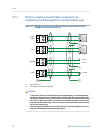
3.3.3 Processor wiring for the remote-mount 2700
FOUNDATION fieldbus
™
option
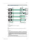
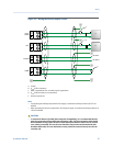
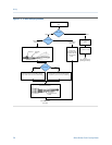
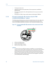
The following figure illustrates how to connect the individual wires of a 4-wire cable to the
processor terminals. For detailed information on mounting and wiring to the remote-
mount 2700 FOUNDATION fieldbus transmitter, see the transmitter installation manual.
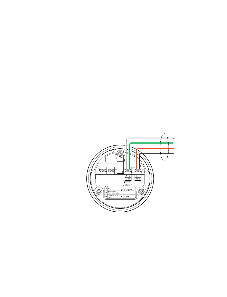
Processor (Modbus/RS-485) connections to the remote-mount 2700 FF
transmitter
Figure 3-5:
A
B
C
D
A. White wire to RS-485/A terminal
B. Green wire to RS-485/B terminal
C. Red wire to Power supply (+) terminal
D. Black wire to Power supply (–) terminal
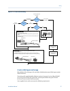
Important
• To meet the EC Directive for EMC (Electromagnetic Compatibility), it is recommended that the
meter be connected using a suitable instrumentation cable. The instrumentation cable should have
individual screen(s), foil or braid over each twisted pair and an overall screen to cover all cores.
Where permissible, the overall screen should be connected to earth at both ends (360° bonded at
both ends). The inner individual screen(s) should be connected at only one end, the controller end.
• Metal cable glands should be used where the cables enter the meter amplifier box. Unused cable
ports should be fitted with metal blanking plugs.
Wiring
38 Micro Motion Fork Viscosity Meter