


3 Wiring
Topics covered in this chapter:
• Available output terminals and wiring requirements
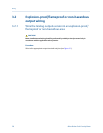
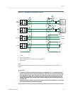
• Explosion-proof/flameproof or non-hazardous output wiring
• Processor wiring for remote-mount 2700 FOUNDATION fieldbus
™
option
• Wiring to external devices (HART multidrop)
• Wiring to signal converters and/or flow computers
3.1 Available output terminals and wiring
requirements
Three pairs of wiring terminals are available for transmitter outputs. These outputs vary
depending on your transmitter output option ordered. The Analog (mA), Time Period
Signal (TPS), and Discrete (DO) outputs require external power, and must be connected to
an independent 24 VDC power supply.
For meters connecting to a remote-mount 2700 FOUNDATION fieldbus
™
transmitter, you
must wire the meter to the remote-mount 2700 transmitter using a 4-wire cable
connection. See the processor wiring content in this manual for information on how to
wire the meter. Refer to the transmitter installation manual for information on wiring the
remote-mount 2700 FOUNDATION fieldbus
™
transmitter.
The screw connectors for each output terminal accept a maximum wire size of 14 AWG
(2.5 mm
2
).
Important
• Output wiring requirements depend on whether the meter will be installed in a safe area or a
hazardous area. It is your responsibility to verify that the specific installation meets the local
and national safety requirements and electrical codes.
• If you will configure the meter to poll an external temperature or pressure device, you must
wire the mA output to support HART communications. You may use either HART/analog
single-loop wiring or HART multi-drop wiring.
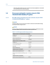
Available transmitter outputsTable 3-1:
Transmitter version
Output channels
A B C
Analog 4–20 mA + HART 4–20 mA Modbus/RS-485
Discrete 4–20 mA + HART Discrete output Modbus/RS-485
Processor for remote-mount 2700
FOUNDATION fieldbus
™
Disabled Disabled Modbus/RS-485
Wiring
Installation Manual 29