


8
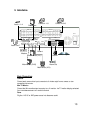
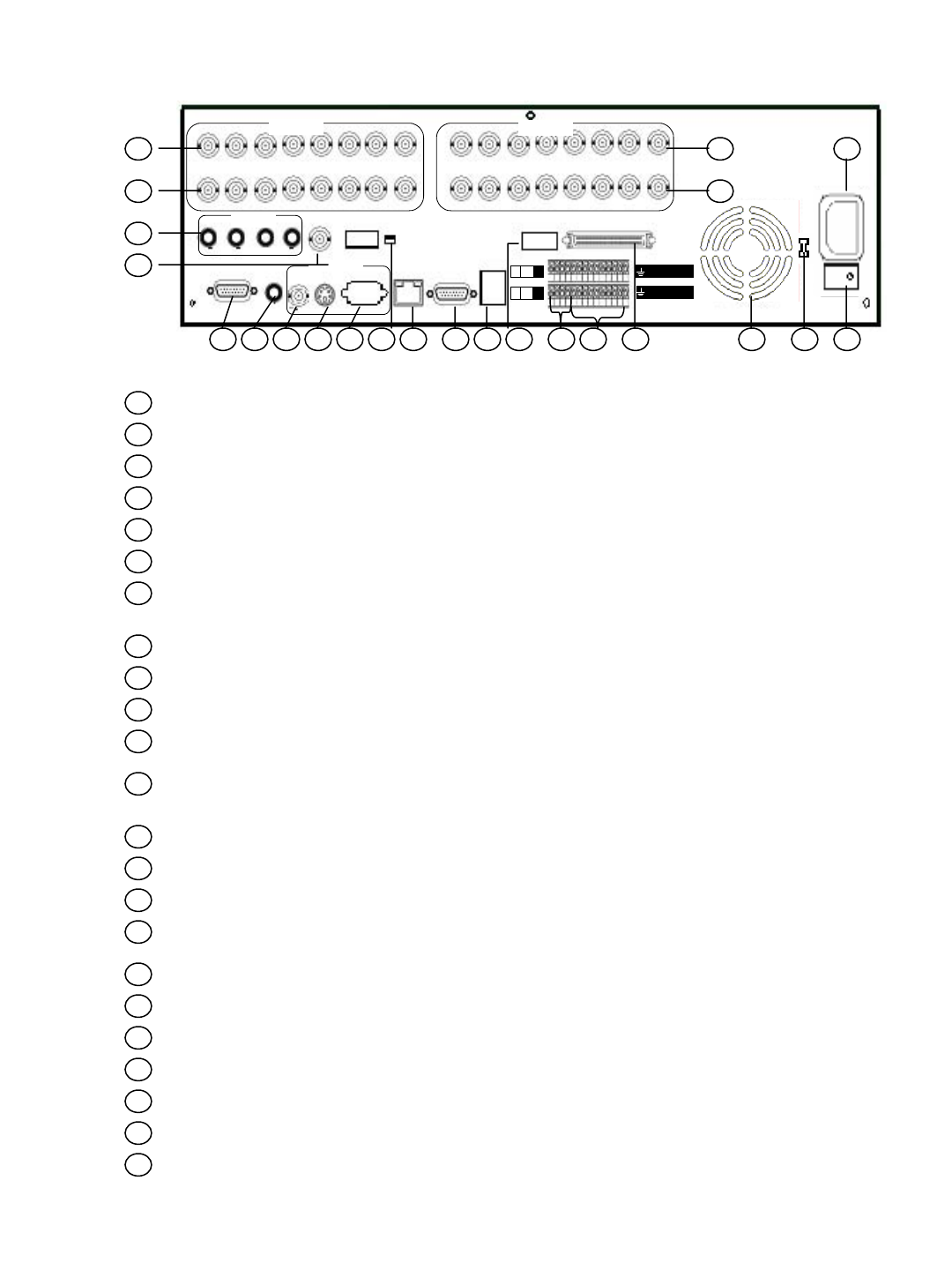
2.2 Back Panel
1
2
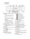
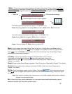
Video Input Connectors (Video In 1-8): BNC connectors for video input 1-8
Video Output Connectors (Video Out 1-8): BNC connectors for video looping out 1-8
4
3
Video Input Connectors (Video In 9~16): BNC connectors for video input 9~16 (eDR1680)
Video Output Connectors (Video Out 9~16): BNC connectors for video looping out 9~16
5
Main Power Socket: The main power input.
6
Power Switch: Power On/Off.
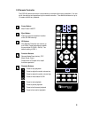
Call Monitor
75
Ω
75
Ω
NTSC/PAL
SCSI
A
udio In
1 2 3 4
In
Out
V1 V2 V3 V4 V5 V6
V7 V8
V9 V10 V11 V12
V13 V14
V15 V16
Video 1-8
In
Out
Video 9-16
RS232#1
Audio
Out
LAN
USB
RS232#2
Power
Alarm In
16 15 14 13 12 11 10
9
8 7 6 5 4 3 2 1
Alarm Out
NO
NC
2 1 C
4 3
6 5 C
8 7
CVBS
Y/C
VGA
Main Monitor
1-8
9-16
15
1
2
12 11
4
53
10 9 8 7 614 131619 18 1720
22
21
23
15
12
11
10
8
7
14
13
16
19
18
17
20
21
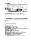
Power Selector Switch: 115V AC or 230V AC selector switch. Warning: To avoid damaging
the system, set this switch before plugging in the power plug. Use a screwdriver to set the
switch to the correct position so that the number shown is the same as the local AC voltage.
Cooling Fan
9
SCSI Connector: For connecting the optional extension unit. (Reserved)
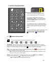
Alarm Inputs: Connect to alarm inputs 1-16 and 2 common grounds
Alarm Outputs: Connect to 4 Normally Closed alarm outputs (1,2,5,6), Normally Open alarm
outputs (3,4,7,8) and 2 common grounds.
75ohm Termination 9-16: The termination should be set as On normally. However, if the
corresponding camera is connected to other devices, please set it as off
USB Connector: Reserved.
RS232 connector #2: Connects to PTZ camera.
Video System Switch
: NTSC / PAL manual switch. Please make sure to select the proper video system
before system starts up
LAN connector: Connects to RJ45 LAN connector.
Main Monitor VGA Output: VGA connector
Main Monitor Y/C Output: Mini-Din S-Video connector
Main Monitor CVBS Output: BNC connector, connects to TV monitor input
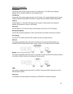
Audio Output Connector (Audio Out): Audio output to an external device (Speakers)
RS232 connector #1: Connects to Modem (Modem Function Reserved)
22
23
Call Monitor Output: BNC connector for Call (spot) monitor
Audio Input Connectors (Audio In 1-4): Audio input from an external device Mick)