


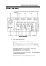

Administrator’s Guide and Operating Instructions
9
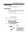
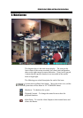
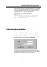
3.2 Basic Connections
Cameras
Connect each of the camera video input connector to the video
output from a camera or other composite video source. At least
one camera must be connected before the system is running for
the auto detection of video standard to take effect.
VGA Monitor
Connect the VGA monitor output connector to a VGA monitor.
The VGA monitor displays selected live or recorded cameras in any
available format.
Mouse
Connect a PS2 mouse to the mouse connector.
Hard Disk(s)
Make sure that at least one hard disk is inside the hard disk trays.
Set HDD#1 as master and HDD#2 as slave. The settings should
be described on the hard disk itself or in the manual come with the
hard disk.
Power
Plug the 115V AC or 230V AC power source into the power socket.
Be sure to set the Power Selector Switch before plugging in the
power plug.
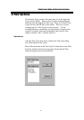
3.3 Optional Connections
Call Monitor
Connect the Call Monitor Output Connector to a TV monitor. This
monitor displays the full screen images of cameras associated with
alarms or images from the installed cameras sequentially.
Alarm In
Connect Alarm In 1-24 to NC or NO type of alarm signals. Please
make sure to setup the software configurations of Alarm In
accordingly.
Alarm Out
Connect Alarm Out 1-4 to NC type of alarm signals, Alarm Out 5-8
NO type.