


Masterpage:Right-No-Heading
EN 11
Filename [DR-M10SE_06Name.fm]
Page 11 February 13, 2004 2:15 pm
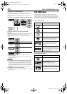
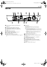
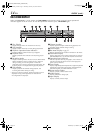
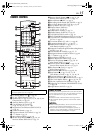
REAR VIEW
A Antenna Input Connector (ANTENNA IN)
੬ pg. 16
B Component Video Output Connectors
(COMPONENT VIDEO OUT )੬ pg. 18
C S-video Output Connector (S-VIDEO OUT)
੬ pg. 17
D Audio Output Connectors
(AUDIO OUT (RIGHT/LEFT)) ੬ pg. 17
E AV COMPU LINK Connector*
* Not function with this unit.
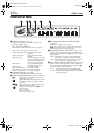
F Digital Audio Output Connectors
(DIGITAL OUT (COAXIAL/OPTICAL)) ੬ pg. 84,
91
G Cooling Fan
● This prevents the temperature from rising inside the unit.
Do not remove it.
● Install the unit so as not to block the area around the fan.
● The cooling fan on the rear of the unit may be activated even if the
unit is turned off in the following cases;
— In the timer Auto Satellite Programme Recording standby mode
੬ pg. 63, slightlybefore the starting time of VPS/PDC recording
੬ pg. 57
— If you record the decoder or the satellite receiver to L-2 IN/
DECODER and if “L-2 SELECT” is set to “DECODER” or “SAT
VIDEO” or “SAT S-VIDEO”.
੬ pg. 83
— “JUST CLOCK” is set to “ON” ੬ pg. 105
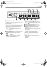
H Mains Power Cord ੬ pg. 16
I Antenna Output Connector (ANTENNA OUT)
੬ pg. 16
J L-1 Input/Output Connector (L-1 IN/OUT)
੬ pg. 16, 81, 82, 88, 90
K L-2 Input/Decoder Connector
(L-2 IN/DECODER) ੬ pg. 26, 81, 88, 90
L Satellite Control Connector (SAT CONTROL)
੬ pg. 26
M Region Number Label ੬ pg. 6
DR-M10SE_06Name.fm Page 11 Friday, February 13, 2004 2:16 PM