


4140
*
1
2
3
*
1
2
3
4
5
6
7
*
.
.
.
*
.
.
.
.
.
.
.
*
S
E
C
[
R
R
D
T
A
R
R
*
R
X
N
A
E
E
U
A
U
E
E
*
I
T
T
L
C
C
R
P
T
P
P
[
/
*
*
A
*
*
A
E
O
E
E
S
E
R
T
R
M
S
T
*
*
A
A
R
X
E
A
M
O
P
I
E
R
T
E
I
T
C
P
/
D
E
O
N
E
*
*
/
*
*
E
S
E
E
N
D
W
P
R
E
R
E
S
E
*
D
*
*
*
L
E
X
E
N
E
N
*
*
*
M
*
A
C
T
C
D
N
S
*
*
*
O
*
Y
*
*
*
*
D
O
*
*
*
D
*
*
*
M
*
*
*
R
*
*
*
E
*
*
*
O
*
*
*
*
*
*
*
*
*
*
*
D
*
*
*
M
*
*
*
*
*
*
*
E
*
*
*
O
*
*
*
*
*
*
*
]
S
N
*
D
*
*
1
*
*
*
*
*
E
O
*
E
*
*
5
*
*
*
*
*
R
R
5
]
*
*
8
*
*
*
*
*
I
M
0
*
O
*
S
O
O
O
O
*
E
A
0
*
F
2
E
F
F
F
F
*
S
L
0
*
F
H
C
F
F
F
F
AC~IN
AC120V~50/60Hz
RS-232C
CAM SW
OUT
ALARM
IN
COM
COM
ALARM
REC OUT
ALARM
RESET
TAPE
END OUT
WARNING
OUT
CLOCK
RESET IN
SERIES
RESET IN
SERIES
RESET OUT
CLOCK
RESET OUT
AC~IN
AC120V~50/60Hz
RS-232C
CAM SW
OUT
ALARM
IN
COM
COM
ALARM
REC OUT
ALARM
RESET
TAPE
END OUT
WARNING
OUT
CLOCK
RESET IN
SERIES
RESET IN
SERIES
RESET OUT
CLOCK
RESET OUT
AC~IN
AC120V~50/60Hz
RS-232C
CAM SW
OUT
ALARM
IN
COM
COM
ALARM
REC OUT
ALARM
RESET
TAPE
END OUT
WARNING
OUT
CLOCK
RESET IN
SERIES
RESET IN
SERIES
RESET OUT
CLOCK
RESET OUT
REMOTE
MIC
IN
OUT
AUDIO
VIDEO
Y/C
REMOTE
MIC
IN
OUT
AUDIO
VIDEO
Y/C
REMOTE
MIC
IN
OUT
AUDIO
VIDEO
Y/C
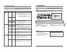
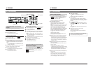
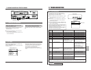
6-6 Series Recording
The series recording function facilitates recording over much longer periods using several connected SR-9090Us.
As soon as the tape ends in one VCR, the next VCR in the series starts recording. Using the counter end output function
enables smoother switchovers during series recording, mostly eliminating interruptions between tapes.
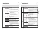
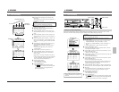
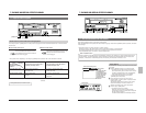
6-5 Sensor Recording
Sensor recording is executed only when the VCR is in the Stop mode (Stop, Timer Record Standby or Operating Off mode)
and an alarm signal is input to the rear panel’s ALARM IN terminal.
Perform the settings for sensor recording in the same way as for “Alarm Recording” on page 39.
The mechanism of the SR-9090U cannot be guaranteed if the sensor recording function is used frequently (100 times/day
or more).
6 RECORDING
6 RECORDING
Preparation
Connect an alarm sensor to the rear panel’s alarm input terminal.
Press the [OPERATE] button to turn the operating mode
on.
Open the main menu’s <ALARM/SENSOR MODE> and
set the sensor recording-related menu switches.
REC MODE
Set to “SENSOR” or “ALL” to activate alarm recording.
• When set to “ALL”, both alarm recording and sensor
recording will be performed.
• The [SENSOR REC] indication lights on the display.
REC SPEED
Select the alarm recording speed from the standard
(2H) mode or the extended EP (6H) mode.
DURATION
Set the sensor recording duration to 5 sec., 10 sec.,
15 sec., 30 sec., 60 sec., 120 sec., 180 sec., TAPE
END (to tape end) or MANUAL (for as long as alarm
signals are input).
* The sensor recording time will be shorter than the
specified value.
* When the sensor recording time is set to
“MANUAL”, the alarm cue signal (index code) will
not be recorded correctly if sensor input lasts for
less than 5 seconds.
* When sensor recording duration is set with an
external switcher, set the sensor recording duration
to “MANUAL”.
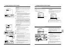
TAPE END MODE
Selects whether or not the Stop mode is forcibly
engaged when the tape ends during sensor
recording.
• When set to “STOP”, the Stop mode is engaged at
tape end even if repeat recording or auto rewind is
set.
• When set to “OFF”, VCR operation is determined by
the repeat recording or auto rewind setting
Set the other menu switches.
5 Setting the alarm buzzer
Set the menu switch <AL/SENSOR IN> in
<BUZZER> to “ON” to sound the alarm buzzer during
sensor recording.
5 Setting the on-screen brightness and display items
Select the monitor display setting with the menu switch.
On-screen information is recorded together with the
video signals.
You can change the on-screen display position with the
[ON SCREEN 7/f] buttons on the front panel.
Turn the operating mode on to engage the Stop mode.
• When an alarm signal is input to the rear panel’s
[ALARM IN] terminal, recording starts automatically in
the specified recording mode (2H or 6H) and the [AL]
indication is lit. The [ALARM] indication is shown on
screen.
• After the specified recording duration expires,
recording stops.
* As sensor recording starts from the Stop mode, it
takes several seconds before actual recording
starts.
To stop sensor recording and clear the [ALARM]
indication, press the [RESET/CANCEL] button.
• In this case, even if the menu switch <TAPE END
MODE> is set to “STOP”, the operation executed at
end of the tape is determined by the setting of the
<AUTO REW> or <REPEAT REC> menu switch in the
<VTR MODE> menu.
To release the Sensor Record mode, set the <REC
MODE> menu switch in <ALARM/SENSOR MODE> to
“OFF” or “ALARM”.
* During playback, there may be some noise or
picture distortion at the point where one sensor
recording stops and another starts. This is not a
malfunction.
* When a new alarm is input during sensor
recording, sensor recording restarts from that
point.
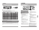
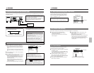
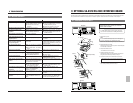
5 Connect the first VCR’s [SERIES REC OUT] terminal to the
second VCR’s [SERIES REC IN] terminal. Connect the
second VCR’s [SERIES REC OUT] terminal to the third
VCR’s [SERIES REC IN] terminal. Repeat for all connected
VCRs. Connect the VCR’s [COM] terminals as well.
5 Connect a video camera and/or other source equipment to the
first VCR’s video and audio input connectors.
Connect the first VCR’s video and audio output connectors to
the second VCR’s video and audio input connectors. Connect
the second VCR’s video and audio output connectors to the
third VCR’s video and audio input connectors.
Repeat for all connected VCRs.
Connect the last VCR’s video and audio output connectors to
the monitor’s video and audio input connectors.
Connections
Video input signal
First VCR
Second VCR
Last VCR
Video output
Rear panel
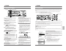
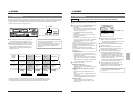
5Normally the next VCR starts recording when the tape
ends. If the menu switch counter end output function is
on, a series recording signal is output when the selected
tape reel counter value is passed, and the next VCR starts
recording. Select the counter end value from “500”,
“1000” ... “9500” with the <CNT TAPE END> menu switch.
• The tape reel counter value from the beginning of the
tape to the end is about 5800 on a T-120 cassette tape.
(Reter to page 64.)
Press the [MENU] button to restore the normal screen.
Load cassettes with safety tab in place in all connected
VCRs.
5 To use the counter end output function, set the
counter to the tape reel counter display with the
[DISPLAY] button.
When a cassette is loaded, the counter is reset to
“0000”.
Start recording on the first VCR.
Audio input signal
Audio output
Monitor TV
First VCR
Second VCR
Third VCR
AC~IN
AC120V~50/60Hz
RS-232C
CAM SW
OUT
ALARM
IN
COM
COM
ALARM
REC OUT
ALARM
RESET
TAPE
END OUT
WARNING
OUT
CLOCK
RESET IN
SERIES
RESET IN
SERIES
RESET OUT
CLOCK
RESET OUT
COM
WARNING
OUT
CLOCK
RESET IN
SERIES
REC IN
SERIES
REC OUT
CLOCK
RESET OUT
COM
WARNING
OUT
CLOCK
RESET IN
SERIES
REC IN
SERIES
REC OU
T
CLOCK
RESET OUT
COM
WARNING
OUT
CLOCK
RESET IN
SERIES
REC IN
SERIES
REC OUT
CLOCK
RESET OUT
REMOTE
MIC
IN
OUT
AUDIO
VIDEO
Y/C
*
1
2
3
*
1
2
3
4
4
2
*
*
.
.
.
*
.
.
.
.
.
.
4
*
S
E
C
[
R
R
D
T
R
W
F
*
R
X
N
A
E
E
U
A
E
A
I
*
I
T
T
L
C
C
R
P
C
R
N
[
/
.
E
A
*
*
A
E
*
N
*
S
E
R
T
R
M
S
T
*
T
I
D
R
X
E
A
M
O
P
O
E
A
N
E
I
T
C
P
/
D
E
N
N
L
G
*
/
*
A
E
S
E
E
*
D
*
M
E
R
E
*
E
D
D
*
*
*
*
E
X
E
N
E
N
*
E
S
M
*
*
N
T
C
D
N
S
*
*
*
O
*
*
U
*
*
*
D
O
*
*
C
D
*
*
*
M
*
*
*
R
*
*
N
E
*
*
*
O
*
*
M
O
*
T
T
*
*
*
*
D
*
*
.
M
4
I
A
*
*
*
E
*
*
*
O
*
5
N
Y
*
*
*
]
*
N
*
D
S
*
E
]
*
*
*
*
*
O
*
E
E
*
6
*
*
*
*
*
*
R
*
]
N
*
0
*
*
*
*
*
O
M
O
*
S
*
S
O
*
*
*
*
F
A
F
*
O
2
E
F
O
O
*
*
F
L
F
*
R
H
C
F
N
N
*
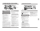
ALARM/SENSOR MODE screen
Operation
To activate series recording, set the <SRI/EXT REC>
menu switch in <SRI/EXT MODE> to “SERIES”.
(This setting should be done for all connected VCRs.)
Notes:
• If a cassette has not been loaded in any VCR in the series, series recording will stop when that VCR is reached.
• If VCRs are connected in series as shown above, the second and subsequent VCRs will record the previous VCR’s on-screen
information in addition to their own. To avoid this, use a distributor to distribute only video signals to each VCR.
• During recording, the input video signals can be checked on a monitor.
• When the second and subsequent VCRs are turned on, input
audio can be checked on the monitor in the 2H/6H modes.
During timelapse recording, audio cannot be checked.
Set to “SENSOR” or “ALL”.
Set to “SERIES”.
Set the counter value.