


1312
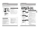
2-3 Rear Panel
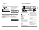
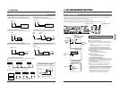
2-1 FRONT PANEL
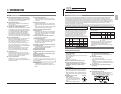
2-3 Rear Panel
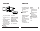
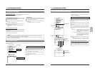
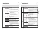
9 [Y/C OUT] connector (4 pin)
Outputs separate Y/C signals.
0 Signal ground terminal
This ground terminal is not provided for safety purposes.
It is used to ground signals. Connect this terminal to
ground the signal between VCRs.
! [CAM SW OUT] camera switching signal output
terminal
When a sequential switcher is connected, this terminal
outputs camera switching timing control signals. For
details on these signals, refer to page 65.
@ [COM] common ground terminal
Connect to the signal ground terminal of a connected
unit.
# [ALARM IN] alarm signal input terminal
Receives signals to start alarm or sensor recording.
$ [ALARM RESET] alarm signal reset input terminal
Receives signals to cancel alarm recording.
* Alarm input data is not reset.
% [ALARM REC OUT] alarm recording mode signal
output terminal
Outputs +12 V signals during alarm recording.
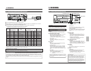
1 [AC IN] connector
Connect to an AC 120 V, 50/60 Hz power outlet using
the provided AC power cable.
2 [REMOTE] remote connector (RCA)
Connect the optional RM-G30U remote control.
3 [MIC IN] mic input connector
Connect a microphone with 3.6-mm dia. plug. When
signals are input from both the microphone connector
and the audio input connector, audio signals are mixed
and recorded.
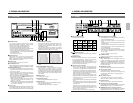
4 [AUDIO IN] audio input connector (RCA)
Receives audio signals from a connected audio source.
5 [AUDIO OUT] audio output connector (RCA)
Outputs audio signals. No signal is output in the
Timelapse Recording/Playback mode.
6 [VIDEO IN] video input connector (BNC)
Receives composite video signals from a connected
camera or other video source.
• For composite video signal input, set the <INPUT>
menu switch in <VIDEO MODE> to LINE.
7 [VIDEO OUT] video output connector (BNC)
Outputs composite video signals. Even when the power
is not supplied to this unit, input signals (composite
video signals) from a camera can be output through this
connector (Operating mode-Off Video Throughout
function).
8 [Y/C IN] connector (4 pin)
Inputs separate Y/C signals.
• For separate Y/C signal input, set the <INPUT> menu
switch in <VIDEO MODE> to Y/C.
2 CONTROLS AND CONNECTORS 2 CONTROLS AND CONNECTORS
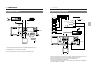
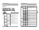
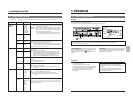
^ [TAPE END OUT] tape end signal output terminal
Outputs a signal when the tape ends during recording.
If the menu switch <CNT TAPE END> on the <SRI/EXT
MODE> screen is set, signals are output when the
specified tape reel counter value is exceeded.
• Outputs a +12 V signal during recording. When the
tape ends or the specified counter value is passed,
a 0 V (GND level) signal is output.
• When the tape ends during auto repeat recording or
auto rewind recording, 0 V signal is output for about 2
seconds.
• Connect an external alarm or buzzer via an external
interface.
• To cancel the output, press the [EJECT] button,
[PLAY] button, [FF] button or [REW] button.
& [COM] common ground terminal
Connect to the signal ground terminal of a connected
unit.
* [WARNING OUT] warning signal output terminal
Outputs warning signals (+12 V) when a tape running or
mechanism problem occurs.
( [CLOCK RESET IN] clock reset input terminal
Connect to a master clock or another SR-9090U’s
[CLOCK RESET OUT] terminal. When the clock reset
signal is input, the time is automatically synchronized
with the master clock or another SR-9090U’s clock.
However, the time difference between VCRs should be
within ±30 seconds.
When the clock reset signal is input, the clock in this unit
is reset as shown below.
• When the seconds value is 29 or less, the minutes
value is the same but the seconds value is reset to 0.
(eg. 12:34:29 —> 12:34:00)
• When the seconds value is 30 or more, the second
value is reset to 00 and the minutes value is increased
by one. (e.g. 12:34:30 —> 12:35:00)
) [CLOCK RESET OUT] clock reset output terminal
Outputs the clock reset signal.
The clock reset signal is output in the following cases.
• When the internal clock is at 0:00 or 12:00
When this unit is connected to another SR-9090U’s
[CLOCK RESET IN] terminal, the other VCR’s clock
can be set to the clock in this unit. However, the time
difference should be within ±30 seconds.
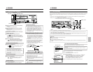
q [SERIES REC IN] series recording/VCR activation
signal input terminal
Receives series recording signal or VCR activation
signal from an external control device.
Select the input signal with the menu switches in the
<SRI/EXT MODE> menu.
5 Series recording input
A series recording signal is input when [SRI/EXT
REC] is set to “SERIES”.
• Connect to another VCR’s series recording signal
output terminal.
• When the tape in the preceding VCR ends, a signal
is delivered to this terminal and recording starts
automatically.
When the menu switch <CNT TAPE END> on the
<SRI/EXT MODE> screen is set, the signals are
delivered when the specified tape reel counter
value is reached. Recording starts automatically.
5 VCR activation signal input
When [SRI/EXT REC] is set to “EXT”, recording is
started and stopped with an external signal.
• Connect to an external control device.
If a VCR activation signal (ground input) is input to
this terminal, the VCR starts recording
automatically and continues recording for as long
as the VCR activation signal is input.
w [SERIES REC OUT] series recording signal output
terminal
Outputs series recording signals.
A series recording signal is output when [SRI/EXT REC]
is set to “SERIES”.
• Connect to another VCR’s series recording signal
input terminal.
• Outputs a signal when the tape being recorded in this
unit ends.
When the menu switch <CNT TAPE END> on the
<SRI/EXT MODE> screen is set, the signals are
output when the specified tape reel counter value is
reached.
AC~IN
AC120V~50/60Hz
RS-232C
CAM SW
OUT
ALARM
IN
COM
COM
ALARM
REC OUT
ALARM
RESET
TAPE
END OUT
WARNING
OUT
CLOCK
RESET IN
SERIES
REC IN
SERIES
REC OUT
CLOCK
RESET OUT
CAM SW
OUT
ALARM
IN
COM
COM
ALARM
REC OUT
ALARM
RESET
TAPE
END OUT
WARNING
OUT
CLOCK
RESET IN
SERIES
REC IN
SERIES
REC OUT
CLOCK
RESET OUT
15
1413
1211
64
3
5
7
10
2
1
8
9
20
1918
17
22
21
16
REMOTE
MIC
IN
OUT
AUDIO
VIDEO
Y/C