


6362
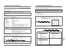
4 Others (Input data correction/Error cancellation)
These are return codes from the SR-9090U. (Error-related codes only)
(1) ERROR (02H) : This is returned when commands of more than 1 byte are transmitted to the VCR and an illegal command is
received in the 2nd byte (or later) of the transmitted command.
In this status, no command can be accepted and only STATUS SENSE will be returned.
To restore normal operation, transmit CLEAR ERROR (41H) or CLEAR (56H) to the VCR.
CLEAR ERROR (41H) : Used to cancel previously-transmitted 1-byte numeric data when inputting
numeric data such as search point. Also used to cancel error status.
CLEAR (56H) : Clears the whole command. Cancels the current status and stops the VCR. Also
cancels the error status.
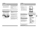
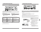
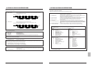
Eg : After setting the recording/playback mode to “L24H”, 32H is mistakenly transmitted . Cancel 32H with
“41H” and input “33H” instead.
(2) NAK (0BH) : VCR will return this code when non-defined or non-functional command is received in the 1st byte of the
transmitted command. In this case, it is not necessary to input CLEAR. Check whether the transmitted command
is acceptable to the VCR or not.
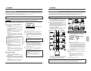
1st byte
BIT Status when BIT is “1”.
0 Error Indicates that an illegal command has been received. No further commands will be accepted.
To restore to normal operation, transmit CLEAR ERROR (41H) to the VCR.
1 Not defined Always 0.
2 Not defined Always 0.
3 Cassette out The tape has not been loaded.
4 REC inhibit A tape with no safety tab has been loaded. In this case, no recording commands
will be accepted.
5 Not defined Always 0.
6 Not defined Always 0.
7 Not defined Always 1.
2nd byte
BIT Status when BIT is “1”.
0 Tape End Tape end sensor is detected.
1 Tape Begin Tape begin sensor is detected.
2 Not defined Always 0.
3 Warning VCR malfunction.
*
4 Not defined Always 0.
5 Not defined Always 0.
6 A EE Mode An externally-input audio signal is being output.
7 V EE Mode An externally-input video signal is being output.
3rd byte
BIT Status when BIT is “1”.
0 Not defined Always 0.
1 Search Mode Search is in progress. (VISS)
2 Repeat Mode Repeat recording is in progress.
3 Not defined Always 0.
4 Repeat VCR’s REPEAT REC menu switch is set to ON.
5 Counter Counter memory is set to ON.
6 Timer REC ON VCR’s TIMER button is set to ON.
7 Not defined Always 0.
4th byte
BIT Status when BIT is “1”.
0 Not defined Always 0.
1 REC Mode VCR is in the Record mode.
2 Eject A cassette is being ejected.
3 Not defined Always 1.
4 Stop Mode VCR is in the Stop mode.
5 REW Mode VCR is in the Rewind mode.
6 FF Mode VCR is in the Fast-Forward mode.
7 PB Mode VCR is in the Play mode.
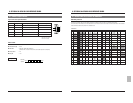
5th byte
BIT Status when BIT is “1”.
0 Speed Code 0 VCR’s current tape running mode. See below.
1 Speed Code 1 VCR’s current tape running mode. See below.
2 Speed Code 2 VCR’s current tape running mode. See below.
3 Speed Code 3 VCR’s current tape running mode. See below.
4 Shuttle REV Reverse search is in progress.
5 Shuttle FWD Forward search is in progress.
6 Not defined Always 0.
7 Rec-Pause Mode VCR is in the Pause mode.
Contents of 5th byte BIT 0/1/2/3 “Speed Code”
Speed Code 3 2 1 0
BIT 0 0 0 0 Still
0 0 0 1 Timelapse playback
0 1 0 1 Timelapse recording/2H (SP)/6H (EP) playback
1 0 0 0 Search (X7 or X13)
1 0 0 1 Search (X21)
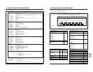
(9) STATUS SENSE (D7H) : The VCR will return current status information in 5 bytes.
* When an error occurs in the VCR and the Warning mode is engaged, the third bit of the second byte sent back with the STATUS
SENSE (D7H) is set to “1”, showing the warning status.
In this case, release the warning via the RS-232C with the CLEAR (56H). To release it on the VCR, turn the [OPERATE] button
off and on again.
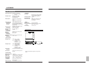
(10) ALARM INPUT (06H) : SR-9090U return code
This is returned when an alarm signal is input during recording.
VCR setting commands
Page
5Recording/playback mode 59
MODE SHIFT 59
MODE 59
5Timelapse VCR operation mode 59
TL STATUS SET 59
5Date and time setting 60
DATE SET 60
TIME SET 60
5Timer programming 60
PRG/CLK 60
SHIFT –/+ 60
SET –/+ 60
CANCEL 60
5On-screen setting 60
ON SCREEN ON/OFF 60
ON SCREEN SELECT 60
POS V+ 60
POS H+ 60
5Others 60
AL/PL RESET 60
COUNT RESET 60
VCR control commands
Page
OPERATE ON/OFF 58
PLAY/REV PLAY 58
STOP 58
FF/REW 58
TIMER ON/OFF 58
OPE ON/OFF 58
EJECT 58
F-FIELD STEP 58
R-FIELD STEP 58
REC CHECK 58
REC/REC PAUSE 58
VISS FWD/REV 58
VISS SEARCH 59
TXD
7EH 30H 32H
RXD
0AH 0AH 0AH
Time
41H
0AH
33H
0AH
40H
0AH
9 OPTIONAL SA-K97U RS-232C INTERFACE BOARD9 OPTIONAL SA-K97U RS-232C INTERFACE BOARD
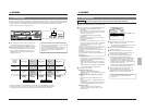
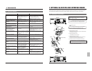
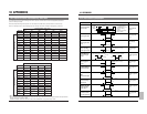
Commands for VCR status verification
Page Byte returned
from VCR
COUNT CODE 61 4 bytes
DEVICE TYPE 61 4 bytes
VTR INQ 61 1 byte
PL/AL COUNT SENSE 61 6 bytes
HOUR METER SENSE 61 4 bytes
TL STATUS SENSE 61 6 bytes
STATUS SENSE 62 5 bytes
DATE SENSE 61 6 bytes
TIME SENSE 61 6 bytes
3 Commands reference chart
Return codes from VCR
Page
ACK 58
NAK 63
ERROR 63
CASSETTE OUT 58
COMPLETION 58
NOT TARGET 58
ALARM INPUT 62
Others
Page
JVC TABLE 1 ON/OFF 58