


66
Chapter
2
File
Menu
910
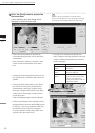
File – Import – Digitizer – Step Scan (When VIVID 910 is Selected)
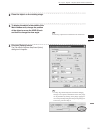
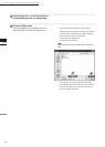
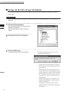
Parameters for [File-Import-Digitizer-Step scan-Option] Dialog Box
Scan Parameter
Mode
Select the scanning mode : FINE or FAST
Scan Parameter
•
Load
: Loads the setting parameters from VIVID 910 and uses them as parameters for this
command.
•
Save
: Saves the parameters set by this command to VIVID 910 as the setting parameters.
Dynamic Range Expan-
sion Mode
If this button is checked, the program takes multiple shots so as to expand the dynamic range and
reduce data loss. This button is displayed only for the VIVID 910.
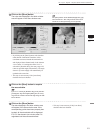
Brightness
Checking this checkbox enables you to set the brightness of the image.
Use Color
Checking this checkbox takes a color shot when a scan is made.
Log
Performs log correction for the color data if this checkbox is checked. This correction is used to
make neutral colors brighter.
Dark
Performs dark correction for the color data if this checkbox is checked. This correction is used
when lines are noticeable in the color image.
Convert Parameter
Save Raw Data
Checking this checkbox displays the data save dialog at the end of the File-Import-Digitizer-
Step Scan command, allowing you to save the data.
Reduction Rate
Used to select the number of data points to be read from “1/1”, “1/4”, “1/9”, “1/16” and “No Polygon”.
Filter • None : Performs no correction for points when reading data. This can be set for
User mode only.
• Noise Filter (N.F.) : Reduces noise in points when reading data.
• High Quarity (H.Q.) : Deletes low-reliable data when reading data.
• H.Q. & N.F. : Reduces noise in points and deletes low-reliable data when reading data.
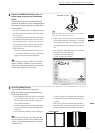
Fill Holes
If “ON” is selected, points are generated in the holes that were produced as a loss of data so that
the holes are lled.
Remove
Select the data to be deleted when reading data.
• None : Outputs the data without performing specic processing.
• Boundary (B.) : Outputs the data after deleting boundary points.
• 5deg & B./10dwg & B./15deg. & B./20deg & B.:
Outputs the data after deleting the points present inside and at the bound
ary of the polygons that are angled within approximately 5, 10, 15 and 20
degrees to the vector of the line of view.
Hardware Parameter • Vertical : Check this checkbox if using the VIVID unit in vertical orientation.
• Horizontal : Check this checkbox if using the VIVID unit in horizontal orientation.
Note
Afterchangingthesettingorientation,theCalibrationChartdataoftherotatingstagemustbeacquired
againbeforemeasuring.
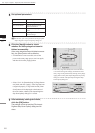
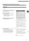
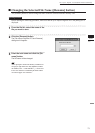
Stage Parameter
Select the Port and Model to be used and click the [Apply] button. The rotary stage will be
initialized. If initialization is successful, the rotary stage can be controlled in the [File-Import-
Digitizer-Step Scan] dialog box.
Rotation Step
Select rotating angle for each step of rotary stage.
Default
Restores the default parameter settings.
OK
Closes the [File-Import-Digitizer-Step Scan-Option] dialog box.
The settings will be set.
Cancel
Closes the [File-Import-Digitizer-Step Scan-Option] dialog box.
The settings will be cancelled.