


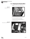
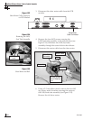
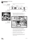
3. Disconnect the skew motor cable from the PCB
module.
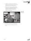
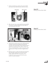
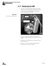
4. Remove the four #8-32 screws securing the
LNB/feed tube assembly to the reflector base (see
Figure 5-41). Withdraw the LNB/feed tube
assembly through the center hole in the reflector.
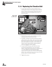
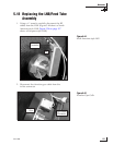
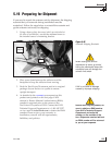
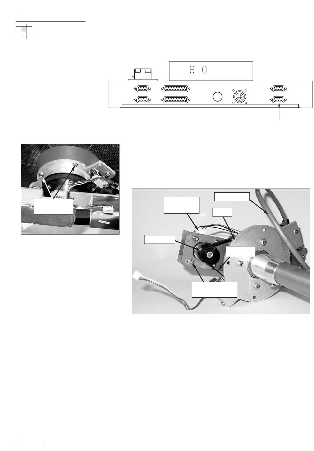
5. Using a 2.5 mm allen wrench, loosen (do not
remove) the four M3 cap screws securing the
motor to the bracket until the motor is free to slide
back and forth (see Figure 5-42). Slide the motor
toward the pulley to loosen the belt.
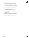
6. Roll the belt over the motor hub, then over the
pulley. Remove and discard the old belt.
7. Place the new belt around the pulley and around
the motor hub. Ensure that the teeth are on the
inside of the belt.
54-0198
118
TracVision G8 Owner’s Manual - Guide to Technical Information
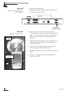
POWER
ELEVATION GYROINTERNAL SENSOR SKEW MOTOR
ELEVATION & AZIMUTH MOTORS
AZIMUTH/ROLL GYROLIMIT SWITCHES
FUSE
Skew Motor
Cable Connector
Figure 5-40
Skew Motor Cable Connector
on PCB Module
Figure 5-42
Skew Motor and Belt
#8-32 Screws
(x 4)
Figure 5-41
Removing the LNB/
Feed Tube Assembly
Pulley
Motor Hub
M3 Cap Screws
(x 4)
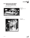
Motor Cable
Connector
Motor Cable
Skew Belt