


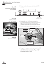
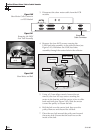
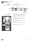

3. European systems only:
Disconnect the skew motor cable from the PCB
module (see Figure 5-46).
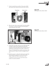
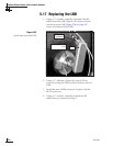
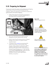
4. Remove the four #8-32 screws securing the
LNB/feed tube assembly to the reflector base (see
Figure 5-47). Carefully withdraw the LNB/feed
tube assembly through the center hole in the
reflector.
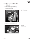
5. Apply a small amount of Loctite threadlocker to
the threads of the four #8-32 screws that you
removed in Step 4.
6. Install the new LNB/feed tube assembly and
secure in place with the #8-32 screws.
7. Reconnect the cables that you removed in Steps 2
and 3.
8. Using a
7
⁄16" wrench, carefully reattach the RF
cables to the LNB.
54-0198
122
TracVision G8 Owner’s Manual - Guide to Technical Information
POWER
ELEVATION GYROINTERNAL SENSOR SKEW MOTOR
ELEVATION & AZIMUTH MOTORS
AZIMUTH/ROLL GYROLIMIT SWITCHES
FUSE
Skew Motor
Cable Connector
Figure 5-46
Skew Motor Cable Connector
on PCB Module
Figure 5-47
LNB/Feed Tube Assembly
#8-32 Screws
(x 4)
LNB
Reflector
Base