


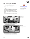
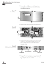
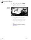

7. Remove the six #6-32 screws and flat washers
securing the main PCB cover to the PCB module.
Set aside the PCB cover.
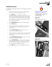
8. Disconnect the three connectors from the main PCB.
9. Using a
3
⁄16" nut driver/socket, remove the two jack
screws from each of the four DB9 connectors and
the two DB25 connectors on the PCB module’s
connector plate.
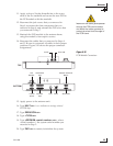
10. Using a
1
⁄4" nut driver/socket, remove the six #6-32
standoffs securing the PCB to the PCB module (see
Figure 5-8). Remove the old PCB.
54-0198
98
TracVision G8 Owner’s Manual - Guide to Technical Information
Figure 5-7
Main PCB Cover
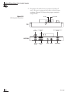
Figure 5-8
Main PCB
Figure 5-9
PCB Module Connector Plate
Jack Screws
Do Not Remove!
Jack Screws
Jack Screws
Standoffs
(x 6)
PCB Connectors
(x 3)
#6-32 Screws
(x 6)