


21. Calibrate the antenna gyros as explained in
“Calibrating the Gyros” on page 105.
22. Reinstall your selected satellites as explained in
Section 2.7, “Installing Satellites Using the MCU,” on
page 42.
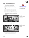
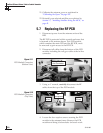
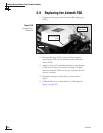
5.7 Replacing the RF PCB
1. Disconnect power from the antenna unit and the
IRD.
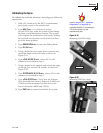
The RF PCB is protected within a metal enclosure that
is fastened to the antenna frame. This PCB module,
which contains the main PCB and the RF PCB, must
be removed to gain access to the RF PCB.
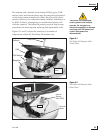
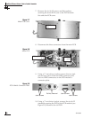
2. Disconnect all cables from the bottom of the PCB
module, including the roll gyro cable at the in-line
connector.
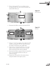
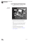
3. Using a
7
⁄16" wrench, carefully disconnect the RF
cables from the top of the PCB module.
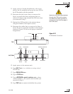
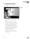
4. Loosen the four captive screws securing the PCB
module to the antenna frame. Remove the PCB
module and bring it belowdecks for bench work.
54-0198
100
TracVision G8 Owner’s Manual - Guide to Technical Information
RF
Connectors
Figure 5-11
PCB Module Connectors
(Bottom View)
Figure 5-12
PCB Module Connectors
(Top View)
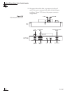
Roll Gyro Cable
In-line Connector
Captive
Screws
Captive
Screws