


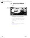

5.6 Replacing the Main PCB
1. With a PC connected to the MCU’s maintenance
port, apply power to the antenna unit.
2. Record the serial number for later re-entry.
3. Disconnect power from the antenna unit and the
IRD.
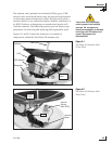
The main PCB is protected within a metal enclosure
that is fastened to the antenna frame. This PCB
module, which contains both the main PCB and the
RF PCB, must be removed to gain access to the main
PCB.
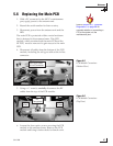
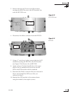
4. Disconnect all cables from the bottom of the PCB
module, including the roll gyro cable at the in-line
connector.
5. Using a
7
⁄
16" wrench, carefully disconnect the RF
cables from the top of the PCB module.
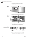
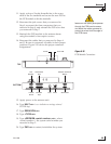
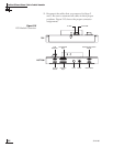
6. Loosen the four captive screws securing the PCB
module to the antenna frame. Remove the PCB
module and bring it belowdecks for bench work.
Maintenance
54-0198
97
RF
Connectors
Captive
Screws
Captive
Screws
Roll Gyro Cable
In-line Connector
Figure 5-5
PCB Module Connectors
(Bottom View)
Figure 5-6
PCB Module Connectors
(Top View)
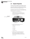
Refer to Section 4.5, “Computer
Diagnostics,” on page 88 for
complete details on connecting a
PC to the system via the
maintenance port.