


11. Apply a drop of Loctite threadlocker to the screw
ends of the six standoffs and secure the new PCB to
the PCB module with the standoffs.
12. Reconnect the jack screws that you removed in
Step 9, reconnect the three connectors that you
removed in Step 8, and reinstall the PCB cover that
you removed in Step 7.
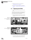
13. Reattach the PCB module to the antenna frame
using the module’s four captive screws.
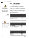
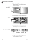
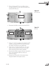
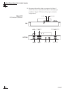
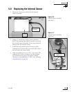
14. Reconnect the cables that you removed in Steps 4
and 5. Be sure to reconnect all cables in their proper
positions. Figure 5-10 shows the proper connector
assignments.
15. Apply power to the antenna unit.
16. Type
HALT<cr> (<cr> indicates a carriage return/
ENTER key).
17. Type
DEBUGON<cr>.
18. Type
=TVG8<cr>.
19. Type
=SERNUM,<serial number><cr>, where
<serial number> = the system serial number you
recorded in Step 2.
20. Type
ZAP<cr> to restart/reinitialize the system.
Maintenance
54-0198
99
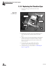
POWER
ELEVATION GYROINTERNAL SENSOR SKEW MOTOR
ELEVATION & AZIMUTH MOTORS
AZIMUTH/ROLL GYROLIMIT SWITCHES
FUSE
Limit
Switches
Internal
Sensor
Azimuth/Roll
Gyro
Elevation
Gyro
Power
Elevation & Azimuth
Motors
Skew MotorFuse
From LNB
BOTTOM
TOP
To IRD
Figure 5-10
PCB Module Connectors
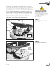
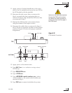
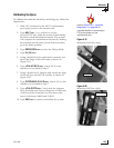
Make sure the cable jacket passes
through the PCB cover’s access
slot within the rubber grommet to
protect the wires from the edge of
the PCB frame.