


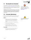
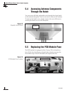
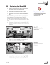

The antenna unit’s printed circuit boards (PCBs), gyros, LNB,
motors, belts, and internal sensor may be removed and replaced
on site using common hand tools. Other TracVision G8 service
must be done by your authorized dealer/installer, distributor, or
by KVH. Evidence of tampering or unauthorized repairs will
void the warranty. The following sections provide step-by-step
procedures for removing and replacing field replaceable units.
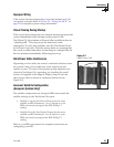
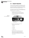
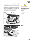
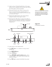
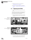
Figures 5-1 and 5-2 depict the locations of a number of
components within the TracVision G8 antenna unit.
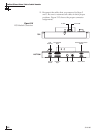
Maintenance
54-0198
95
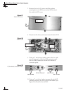
TracVision G8 components
receive power from multiple
sources. Do not open any
electrical assemblies or attempt
servicing until IRD power and
vessel input power are
disconnected.
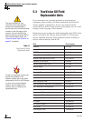
Figure 5-1
TracVision G8 Antenna Unit
(Front View)
PCB Module
Feed Tube
Reflector
Elevation
Motor
LNB
Internal
Sensor
(with GPS)
Azimuth
Motor
Azimuth
FOG
Frame
Baseplate
Figure 5-2
TracVision G8 Antenna Unit
(Rear View)