


14
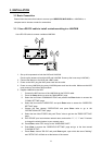
3.3 System Information
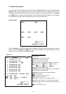
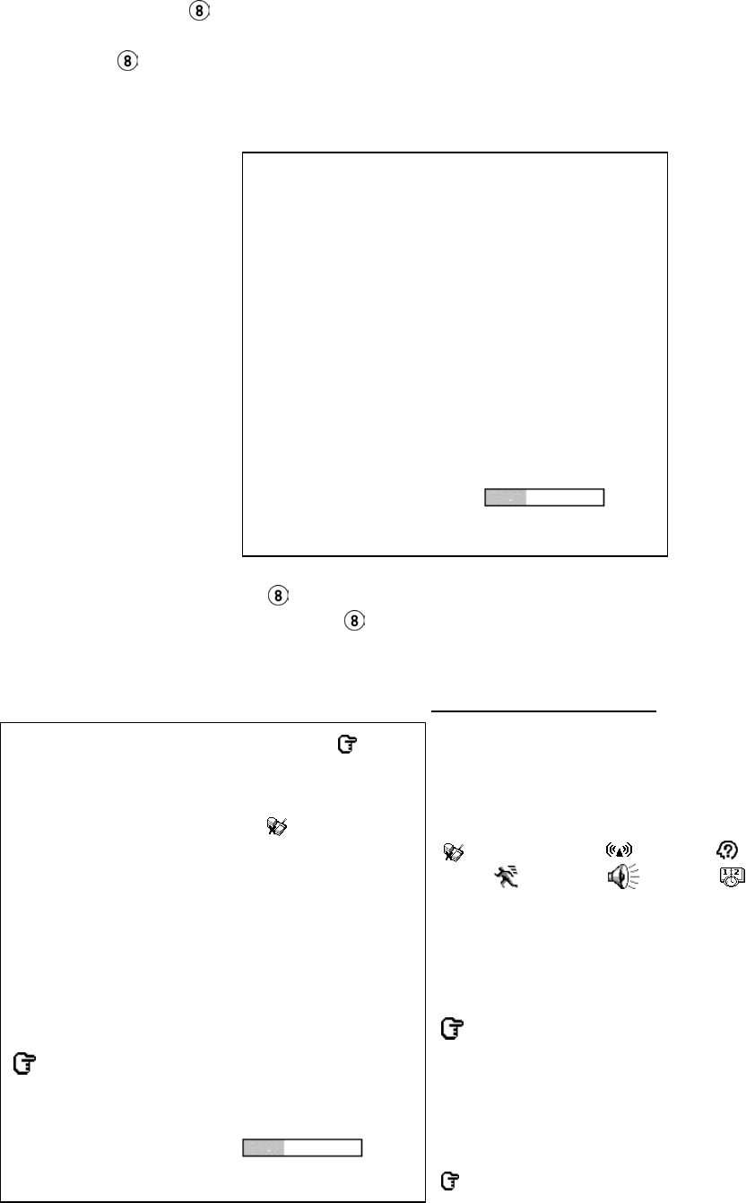
You can display system settings information as shown on Table 3.3 A below at any time by pressing the
Display button
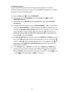
. In the playback mode, the recorded video information is displayed. In the live or
recording mode, the Manual Recording information is displayed. Each sequential press of the Display
button
displays a different message detailed in the following example. By default, the unit displays
time, date, and an indicating bar of capacity status on a monitor as shown next.
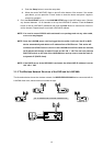
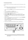
Default display
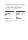
Press the Display button
once; the NVR will display the following sample message plus the default
display. Press the Display button
again; the unit will not display any OSD message. Press the
button one more time to back to the default display.
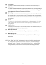
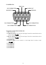
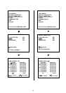
Table 3.3 A. Description of Table 3.3 A
(CH): Channel
(LANCAM IP): LAN Camera IP address
(LIVE): The LAN Camera activated
(OFF): The LAN Camera inactivated
(19): The channel current display speed rate, 19 images/sec
(
):Disconnection; ( ):Alarm; ( ):login error;
(
):motion; ( ):Audio; ( ):Timer
(227K): The LAN Camera bandwidth
(LANCAM IP : 192 . 168 . 001 . 205): Setting of the Ethernet
communication,192.168.001.205
(DHCP:OFF): Only use manual setup IP address
(NTSC): NTSC system
( ): Indicate which HDD is activated
(HD): Hard disk Compartment
(SIZE 20G): The capacity of the installed hard disk
(POS): Percentage of system; R: Recording; P: Playback
11 HR (HD1): Per minute change showing the total recording
time.
(
X): Cannot operate at now
CH LANCAM IP X
1 192.168.001.250 LIVE
2 192.168.001.020 LIVE
3 192.168.001.030
- - -
4 192.168.001.040 OFF
5 192.168.001.050 OFF
6 192.168.001.060 OFF
7 192.168.001.070 OFF
8 192.168.001.080 OFF
IP : 192.168.001.205 DHCP:OFF NTSC
HD SIZE POS
1 20 G 39.5% R 11 HR (HD1)
2 39 G 0.0% P
04-09-2003 12:48:19
CAM1 CAM2
CAM3 CAM4 CAM5 CAM6
CAM7 CAM8
04-09-2003 12:48:19