


11
MAINTENANCE
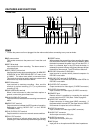
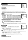
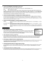
1 DISPLAYING THE POWER LOSS LIST (POWER LOSS LIST)
Turn the JOG dial to select “POWER LOSS LIST”. Turn the SHUTTLE ring to the right to display the
Power Loss List. Power failure start times are stored in memory, so it is possible to confirm when
they have occurred. Up to 3 power failure start times will be displayed. If more than 3 failures have
occurred, the first and last 2 power failure start times will be displayed.
2 DISPLAYING THE ALARM LIST (ALARM LIST)
Turn the JOG dial to select “ALARM LIST”. Turn the SHUTTLE ring to the right to display the Alarm List. Alarm record start
times are stored in memory, so it is possible to confirm when they have occurred. Up to 3 alarm record start times will be
displayed. If more than 3 alarm records have occurred, the first and the last 2 alarm record start times will be displayed.
3 INITIALIZING ALL MENU SETTINGS (ALL MENU INITIALIZE)
Turn the SHUTTLE ring to the right and “ALL MENU INITIALIZE” will be displayed. When the SHUTTLE ring is turned to the left,
each setting is initialised except the TIMER RECORDING setting. When the SHUTTLE ring is turned to the right, the
“MAINTENANCE” menu will be displayed.
4 CLEARING THE POWER LOSS LIST (POWER LOSS LIST CLEAR)
Turn the SHUTTLE ring to the right and “POWER LOSS LIST CLEAR” will be displayed. When the SHUTTLE ring is turned to
the left, the Power Loss List is cleared. When the SHUTTLE ring is turned to the right, the “MAINTENANCE” menu will be
displayed.
5 CLEARING THE ALARM LIST (ALARM LIST CLEAR)
Turn the SHUTTLE ring to the right and “ALARM LIST CLEAR” will be displayed. When the SHUTTLE ring is turned to the left,
the alarm list is cleared. When the SHUTTLE ring is turned to the right, the “MAINTENANCE” menu will be displayed.
0
0H
<
MAINTENANCE
>
POWER LOSS LIST
ALARM LIST
ALL MENU INITIALIZE
POWER LOSS LIST CLEAR
ALARM LIST CLEAR
<
REPEAT REC TIMES
>
<
ELAPSED TIME
>
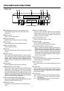
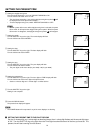
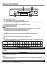
2 SETTING THE FREQUENCY DIVISION RATIO (CLOCK OUT)
Sets the frequency division ratio of the CLOCK OUT terminal.
First, set the recording mode for the “CLOCK OUT” pulse output in the “REAR TERMINAL” menu.
REC: When recording in any mode.
T/L-REC: When recording in time lapse mode (L12H, L24H, 48H, 72H, 96H, 120H, 168H, 240H, 360H, 480H, 720H, 960H or 0H).
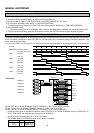
Second, select the frequency division ratio setting by turning the SHUTTLE ring. When the JOG dial is turned, the display will be
switched in the order of 1 } 2 } 3 } 4 } 5 } 10 } 15 } 20 } 25 } 30 } 50 } 60 } F (field) } 1 } ... The numbers from 1
to 60 indicate the number of frames in 3H recording mode or the number of fields in time lapse recording mode. (One frame
consists of two fields.) One field is selected when it is set to “F” (field).
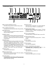
3 SETTING THE OPERATION MODE OF THE MODE OUTPUT TERMINAL (MODE OUT)
Set the state in which the signal output at the MODE OUT terminal is switched to the active condition. When the JOG dial is
turned, the display will be switched on in the order of REC(recording) } PLAY(playback) } POWER (power “ON”) } TAPE IN
(tape is inserted) } TAPE REMAIN (3 minutes in 3H mode before the tape end) } CLOCK ADJ (output the signal for 1 second
when the clock indicates “00(min.):00(sec.)”) } REC
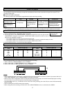
4 SETTING THE OPERATION MODE OF THE REC IN TERMINAL (REC IN)
SERIES: Recording starts when the REC IN terminal is short-circuited to ground or a “L” level voltage (0 - +1.6V) is
applied.
REC-START/ STOP: Recording starts when the REC IN terminal is short-circuited to ground or a “L” level voltage (0 - +1.6V) is
applied. Should this connection be removed, recording will stop.
SYNC REC: The video signal from 5 or 9 cameras can be recorded separately by connecting a switcher. (“SYNC REC”
function is available when recording in L12H or L24H mode.) Refer to “SYNCHRONOUS RECORDING” on
page 18.