


28
NN
NN
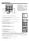
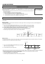
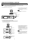
N Before connecting the hardware, unplug the power cord of the VCR from the wall
outlet, and turn the personal computer power off.
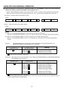
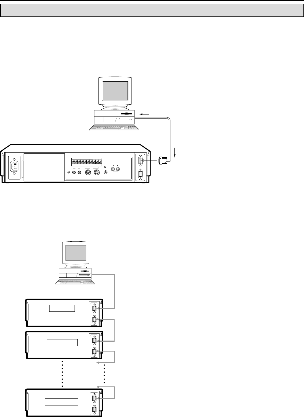
1 Connecting the VCR to a personal computer.
USING WITH THE PERSONAL COMPUTER
Personal computer
To RS-232C
IN terminal
RS-232C cross cable
To RS-232C terminal
OUT
IN
RS-232C
VIDEO
OUTIN
IN
OUT
AUDIO
RESET
SET RST
IN
RECGNDALMMODE CLK CALL
OUT
ÉMIC
REMOTE
IN OUT
S-VIDEO
Personal computer
To RS-232C IN terminal
To RS-232C OUT terminal
To RS-232C IN terminal
To RS-232C IN terminal
To RS-232C OUT terminal
RS-232C cross cable
RS-232C cross cable
RS-232C cross cable
To RS-232C terminal
To RS-232C IN terminal
To RS-232C OUT terminal
RS-232C cross cable
1st VCR
2nd VCR
16th VCR
OUT
IN
RS-232C
OUT
IN
RS-232C
OUT
IN
RS-232C
a. Connect the RS-232C cross cable to the RS-
232C terminal of the personal computer.
b. Connect the other end of cable to RS-232C IN
terminal on the VCR.
NN
NN
N
• Refer to page 30 for the RS-232C cable
configuration.
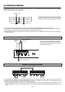
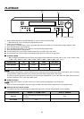
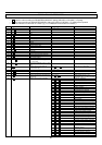
2 Connecting multiple VCRs to a personal computer.
Up to 16 VCRs may be controlled either individually or as a group. To do
this, connect the VCRs in series through the RS-232C IN and OUT
connectors of the interface board.
a. Connect the RS-232C cross cable to the RS-
232C terminal on the personal computer.
b. Connect the other end of the cable to the RS-
232C IN terminal to the 1st VCR.
c. Connect the end of the RS-232C cross cable
to the RS-232C OUT terminal of the 1st VCR
and the other end to the RS-232C IN terminal
of the 2nd VCR.
d. Continue this process until the last (up to 16)
VCR is connected.
NN
NN
N
• RS-232C OUT terminal should be connected
to a time lapse VCR with RS-232C interface
board. This terminal can not be used to
connect to other general equipment with RS-
232C connector.
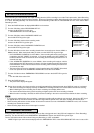
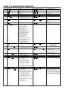
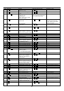
CONFIGURING THE TIME LAPSE VCR