


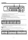
29
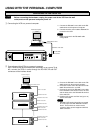
Set the RS-232C interface board setting by using the on screen menu of the VCR.
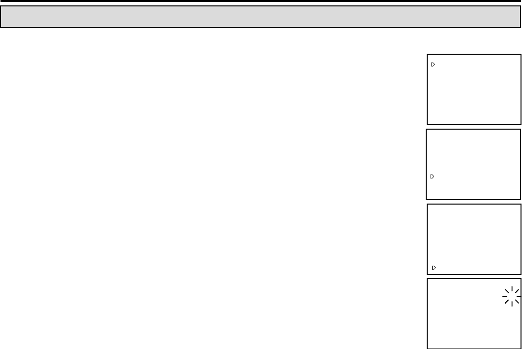
1 Press the DISPLAY button to display MAIN MENU.
• “MAIN MENU” will appear.
2 Turn the JOG dial to select “FIRST TIME SET UP”.
3 Turn the SHUTTLE ring to the right .
•“FIRST TIME SET UP” menu will appear.
4 Turn the JOG dial to select “RS-232C”.
• If “RS-232C interface board” is installed correctly, “RS-232C” item willappear on
“FIRST TIME SET UP” menu.
NN
NN
N
• If the “RS-232C” item does not appear, press the RESET button on the rear panel of
the VCR.
5 Turn the SHUTTLE ring to the right .
•“RS-232C” setting menu will appear.
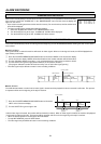
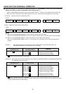
Select the parameter to be changed by using the SHUTTLE ring. Change its value
using the JOG dial and then use the SHUTTLE ring to store the new value.
1 SETTING TRANSMISSION RATE
When the JOG dial is turned to the right, the display will be switched in the order of 1200(bps) } 2400(bps) } 4800(bps)
}9600(bps) } 1200(bps) } ....
2 SETTING DATA BIT LENGTH
When the JOG dial is turned to the right, the display will be switched in the order of 8 BIT } 7 BIT } 8 BIT } ....
3 SETTING STOP BIT LENGTH
When the JOG dial is turned to the right, the display will be switched in the order of 1 BIT } 2 BIT } 1 BIT } ....
4 SETTING PARITY BIT
When the JOG dial is turned to the right, the display will be switched in the order of NONE } ODD } EVEN} NONE } ....
NN
NN
N
• The Parity bit cannot be used when the DATA BIT LENGTH is set to 8.
5 SETTING DELIMITER<SEND> (Setting a character marking the end of a command.)
When the JOG dial is turned to the right, the display will be switched in the order of CR } CR•LF } CR } ....
6 SETTING DELIMITTER<RECEIVE> (Setting a character marking the end of a status or error code.)
When the JOG dial is turned to the right, the display will be switched in the order of CR } CR•LF } CR } ....
7 SETTING VCR ADDRESS (Setting the ID number of the VCR)
When the JOG dial is turned to the right, the screen display will be switched in the order of NONE } VCR01 } VCR02} VCR03
} ... } VCR14 } VCR15 } VCR16} NONE } ....
• When controlling only one VCR via the personal computer, “VCR ADDRESS” is set to “NONE”.
• When two or more VCRs are to be controlled in series, each VCR must have a unique VCR ADDRESS (from VCR01 to
VCR16).
NN
NN
N
• Set the communications parameters (items 1 - 6 above) to the same values as the controlling personal computer or other
equipment. Each VCR must have the same settings when multiple VCRs are connected.
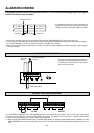
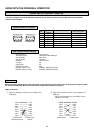
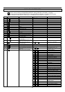
<
MAIN MENU
>
DISPLAY
TIME DATE SEARCH
TIMER PROGRAM
RECORDING SET UP
REAR TERMINAL
MAINTENANCE
FIRST TIME SET UP
Use JOG to select,
and ENTER.
Press DISPLAY to exit.
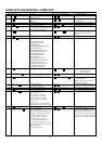
<
MAIN MENU
>
DISPLAY
TIME DATE SEARCH
TIMER PROGRAM
RECORDING SET UP
REAR TERMINAL
MAINTENANCE
FIRST TIME SET UP
Use JOG to select,
and ENTER.
Press DISPLAY to exit.
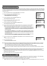
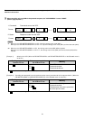
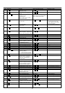
<
FIRST TIME SET UP
>
TAPE END
QUASI V-SYNC
TAPE LENGTH
VIDEO MODE
PB HEAD SELECT
BUZZER
TIME DATE ADJUST
RS-232C
STOP
ON
E-180
COLOUR
NORMAL
WRNG
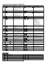
<RS-232C>
TRANSMISSION RATE
DATA BIT LENGTH
STOP BIT LENGTH
PARITY BIT
DELIMITTER<SEND>
DELIMITTER<RECEIVE>
VCR ADDRESS
1200
8BIT
1BIT
NONE
CR
CR
NONE
RS-232C SETTING