


13
Part II: Installation
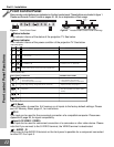
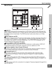
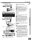
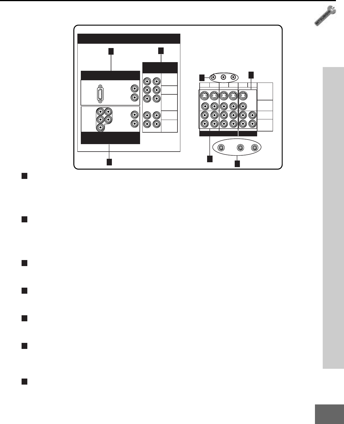
Back Panel Functions
1
Inputs 1-4
These inputs can be used for the connection of a VCR, Super VHS (S-VHS) VCR, laser disc
player, or other A/V device to the TV. Please note that if you connect to the S-VIDEO terminal,
the VIDEO terminal is deactivated. The VIDEO terminal is active when there is no S-Video
connection.
2
Output (Monitor and PIP)
The Monitor Output sends the TV audio and video signals, excluding component video, PC, or
DTV video, to an A/V receiver or other equipment. The PIP output sends the PIP’s or POP’s
audio signal to an amplifier or wireless headphones. If no PIP or POP is displayed, the PIP
output will send the main picture audio signal.
3
Antenna (ANT-A, LOOP OUT, and ANT-B)
ANT-A and ANT-B receive signals from VHF/UHF antennas or a cable system. LOOP OUT
sends the ANT-A signal out to another component, such as a cable box or VCR.
4
IR-Emitter (System 4 Home Theater IR Control)
Connecting an IR emitters here allow the TV to automatically change a digital A/V receiver’s
input in a home theater setup, and pass IR commands to other A/V devices.
5
Component Inputs 1-2
These inputs can be used for the connection of A/V equipment with component video
devices, such as a DVD player. Please see
Appendix B
, page 59, for signal compatibility.
6
DTV Input
This input is used to connect a DTV receiver, and can be configured for HDTV component
video (Y/Pb/Pr), RGB Sync on green, or RGB plus H&V. Please see
Appendix B
, page 59, for
signal compatibility.
7
PC-1
This input can be used for the connection of a computer. Please see
Appendix B
, page 59, for
signal compatibility.
60 Hz
Y/G
AUDIO-L
AUDIO-L
(MONO)
AUDIO-R
AUDIO-L
(MONO)
AUDIO-R
LOOP
OUT
IR - EMITTER
ANT-BANT-A
12
12
S-VIDEO
VIDEO
3 4 PIP
MONITOR
Pr
Y
Pb
AUDIO-R
AUDIO-L
AUDIO-R
P
r
/R
H
V
P
b
/B
PC - 1
VGA / SVGA / XGA
COMPONENT
480i / 480p
HIGH RESOLUTION INPUTS
INPUT OUTPUT
DTV
1080i / 720p / 480i / 480p
7
5
4
2
3
1
6
Back Panel