


21
Part II: Installation
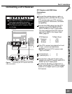
Connecting a DTV Receiver
Connecting a DTV Receiver
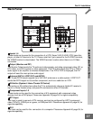
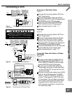
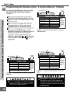
Figure 1. Connecting the DTV receiver with RGB
video connections.
DTV Receiver with RGB Video
Connections
(Figure 1)
1
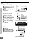
Connect the outside antenna, cable, or
satellite to ANT, or SATELLITE IN on the
DTV receiver (see your DTV receiver’s
owner’s guide for instructions, and cable
compatibility).
Connect the RGB cables from the DTV
receiver to the HIGH RESOLUTION
INPUT GRBHV on the TV back panel.
You may need to set the DTV input as-
signment to RGB in the
Assign Input
Menu
, page 33.
DTV Receiver TV Back Panel
2
G (green) = Y/G
3
R (red) = Pr/R
4
B (blue) = Pb/B
If the DTV receiver has outputs for H and
V sync, connect as listed below
(DO NOT connect if DTV receiver uses
“Sync on Green”):
5
H
(horizontal sync)
= H
6
V (vertical sync) = V
7
Connect the L (left) and R (right) audio
cables from the DTV receiver and to DTV
AUDIO on the TV back panel.
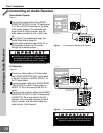
To utilize the benefits of a digital A/V re-
ceiver, connect your DTV receiver’s digital
audio out to a digital input on your digital
A/V receiver.
60 Hz
Y/G
AUDIO-L
AUDIO-L
(MONO)
AUDIO-R
LOO
P
OU
T
IR - EMITTER
ANT-A
12
1234
MO
N
Pr
Y
Pb
AUDIO-R
AUDIO-L
AUDIO-R
Pr/R
H
V
P
b/B
PC - 1
VGA / SVGA / XGA
COMPONENT
480i / 480p
HIGH RESOLUTION INPUTS
INPUT
O
DTV
1080i / 720p / 480i / 480p
AUDIO
L
R
H
V
G
R
B
S-VIDEO
VCR
CONTROL
DIGITAL
AUDIO OUT
PHONE JACK
RF
REMOTE
SATELLITE IN
IN FROM ANT
OUT TO TV
CH 3
CH 4
CAUTION
RISK OF ELECTRICAL SHOCK
DO NOT OPEN
3
2
2
2
3
White
Red
TV back panel
2
2
2
5
6
3
3
5
6
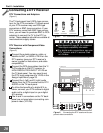
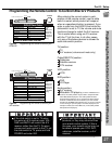
See
Appendix B
, page 59, for component
video signal compatibility information.
For digital audio connections, see your
DTV receiver and A/V receiver Own-
er’s Guides.