


6. NetCommand 55
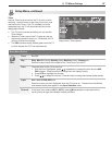
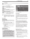
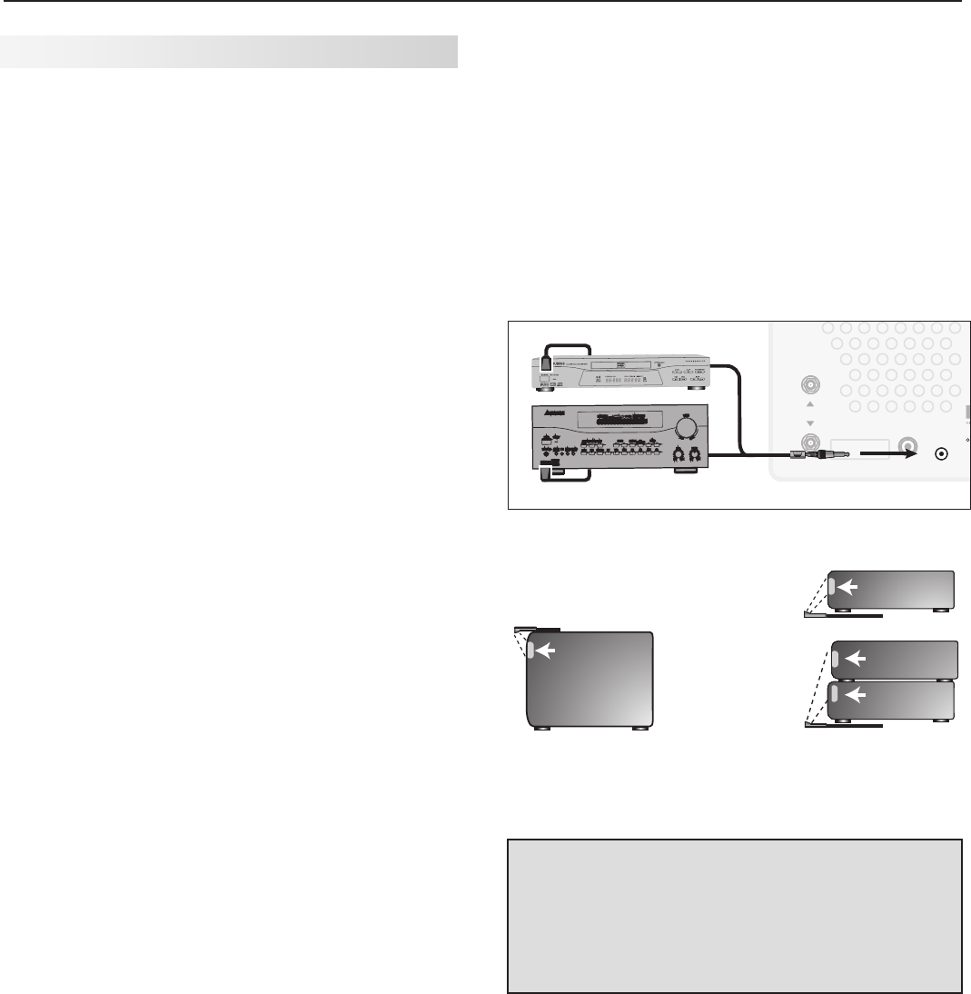
IR Emitter Placement (NetCommand)
An IR emitter cable is included with the TV.
TheNetCommandsystemusesemittersconnectedto
the
IR EMITTER
jacktocontrolotherdevicessuchas
DVDplayers,cableboxes,satellitereceivers,andVCRs.
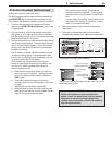
1. ConnecttheplugendofthesuppliedIRemitter
cabletothe
IR EMITTER NetCommand
®
jackonthe
TVbackpanel.
2. Runthecableforeachoftheemitterendsunder,
alongside,orovereachdevicetobecontrolledso
thattheemitterendisinfrontoftheareawherethe
remotecontrolsensorislocated.
3. Positiontheemitterendwiththeemitterbulbfacing
theremotecontrolsensor.Thebulbemitsinfrared
lightinacone-shapedpattern.Placethebulbfar
enoughfromthesensortoallowtheconepattern
toreachthesensor.
TheIRsensorisusuallybehindtheplasticwindow
ofthefrontdisplaypanel.Itissometimesvisible
withtheaidofaflashlightandisnormallyaround
orsquarecutoutbehindtheplastic.
Ifyoucannotseethesensorandthedevice’s
Owner’sGuidedoesnotspecifythelocation,you
canfinditbyfollowingthesestepsusingthe
device’sremotecontrol:
a. Holdthedevice’sremoteaboutone-halfinch
fromthefrontofthedevice.Startingfromone
endofthedisplaywindowplastic,pressthe
POWER
button.
b. Ifthedevicedoesnotrespond,movethe
remotecontroloneinchtowardthecenterand
tryagain.
c. Repeatthisuntilthedeviceresponds.
d. Notethislocationandthenstartoverfromthe
otherendofthedisplaywindowplastic,repeat-
inguntilthedevicerespondsagain.
Theremotecontrolsensorissomewhere
betweenthesetwopositions.Thisisusually
enoughaccuracyforplacementoftheIRemit-
ters.
Insomecases,theemitterworksbetterfacing
downwardfromthetopofthedevice.Experi-
menttofindwhatworksbest.
4. Securetheemitterendsinplaceusingdouble-
sidedtape.
5. Placeanyunusedendsbehindthedevicesto
preventstraysignalsfromreachingtheIRsensors.
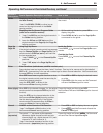
INPUT 1
INPUT 2
L
(MONO) R
AUDIO
DIGITAL
AUDIO
OUT
HDMI
1
2
Y
Pb
Pr
AVR
AUDIO
OUTPUT
S-VIDEO
VIDEO
3
L (MONO) - AUDIO - R
Y Pb Pr (480i/480p/720p/1080i)
VIDEO: 480i /480p /720p /1080i /1080p
AUDIO: PCM STEREO
PC: VGA / W-VGA / SVGA / W-SVGA /
XGA / W-XGA / SXGA / 720p /1080p
IR EMITTER
NetCommand
R
PC/DVI
AUDIO
INPUT
COMPONENT 1
COMPONENT 2
ANT 2 / AUX
ANT 1 / MAIN
IR EMITTER
NetCommand
R
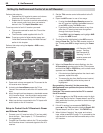
57#BDL1BOFM
%*(*5"-
463306/%
4
$)
"73FDFJWFS
0UIFS"7%FWJDF
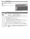
Connecting IR Emitter NetCommand
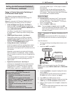
*OGSPOUPGB
TJOHMFBWFSBHF
TJ[FEEFWJDF
0OUPQPGBTJOHMF
UBMMEFWJDF
*OGSPOUTIBSFE
CZUXPBWFSBHF
TJ[FEEFWJDFT
*3TFOTPS
*3TFOTPS
*3TFOTPS
*3TFOTPS
*OGSPOUPGBTJOHMF
BWFSBHFTJ[FEEFWJDF
0OUPQPGBTJOHMFUBMM
EFWJDF
*OGSPOUTIBSFECZUXP
BWFSBHFTJ[FEEFWJDFT
*3TFOTPS
*3TFOTPS
*3TFOTPS
*3TFOTPS
*3TFOTPS
*OGSPOUPGBTJOHMF
BWFSBHFTJ[FEEFWJDF
0OUPQPGBTJOHMF
UBMMEFWJDF
*OGSPOUTIBSFECZ
UXPBWFSBHFTJ[FE
EFWJDFT
*3TFOTPS
*3TFOTPS
*3TFOTPS
*3TFOTPS
*3TFOTPS
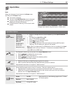
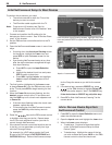
Place IR emitters so the signal can be “seen” by the IR
sensor on each device.
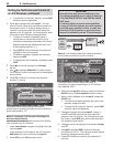
IMPORTANT
Position IR emitters so that each device’s
sensor “sees” the signal from only one emitter.
Otherwise, a device receiving signals from
multiple sources (remote controls, IR emitters)
may not respond at all.
Place the emitter ends in front of each device
to be controlled and in the area where the
remote control sensor is located.