


10
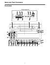
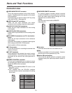
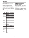
Connector area
Parts and Their Functions
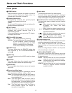
Pin No. Signal
1 Frame Ground
2 Transmit A
3 Receive B
4 Receive Common
5
6 Transmit Common
7 Transmit B
8 Receive A
9 Frame Ground
1
6
9
5
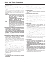
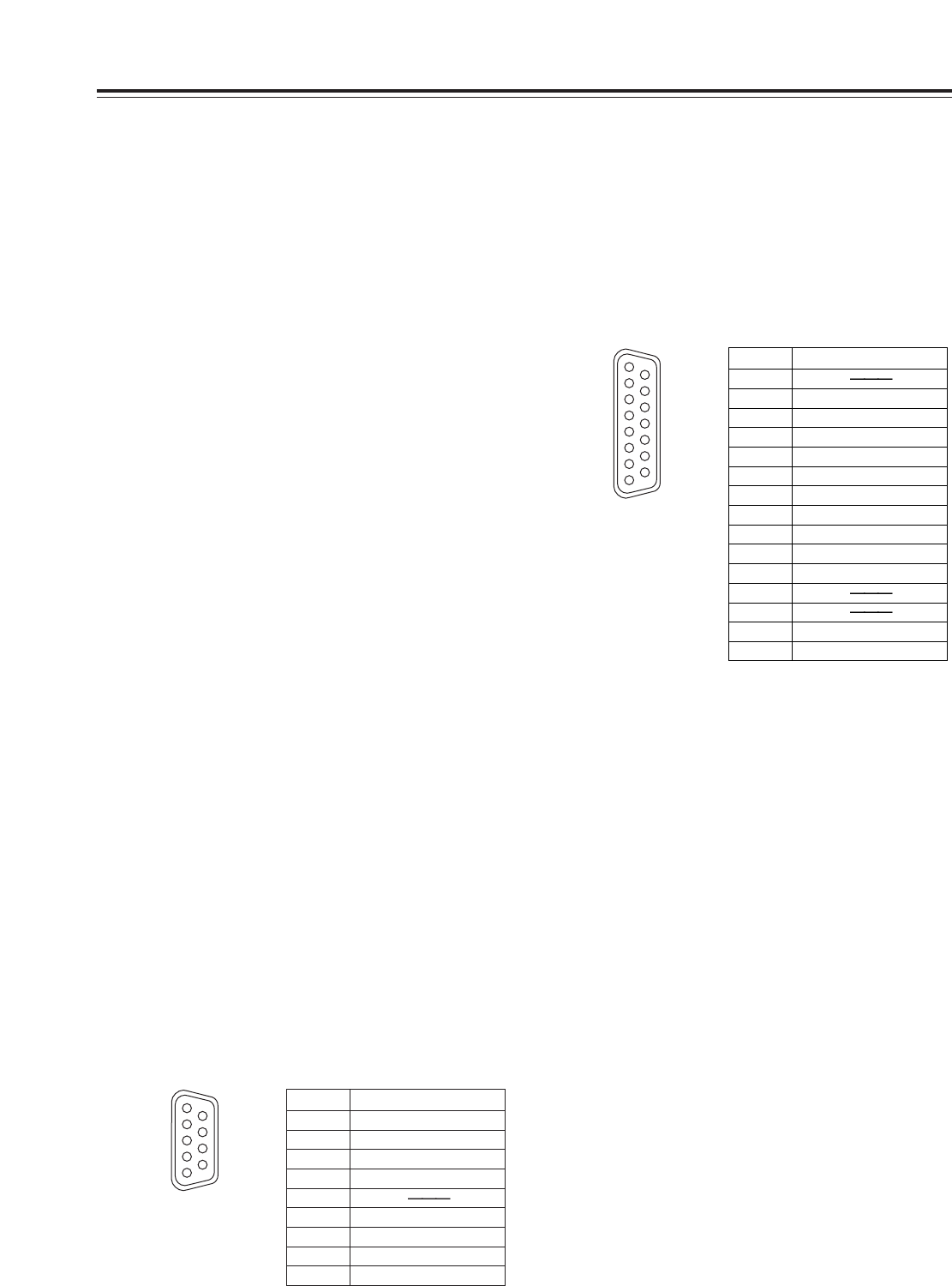
Pin No. Signal
1
2 Set Up
3 C Level
4 Ground
5 +9 V
6 System H
7 SYS. SC. Coarse (2)
8 –9 V
9 Hue
10 Video Level
11 Ret Ground
12
13
14 SYS. SC. Fine
15 SYS. SC. Coarse (1)
1
8
9
15
?
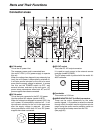
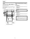
Fan motor
This motor drives the fan to cool down the unit.
@
Grip
Grips are provided on the side panels. However,
when the unit is to be operated, lay it flat.
A
Slot for SDI card (option)
This is the slot for the optional component serial
interface board (SDI input/output board: model AJ-
YA95P).
6
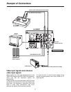
VIDEO MONITOR OUT connector
This is the output connector for the video monitor
signals. Superimposed video signals can be output
to this connector.
Superimposing can be set to ON or OFF by setup
menu item No.002. (See page 29)
7
VIDEO IN and OUT connectors
These are the input connector and output
connectors for the analog composite video signals.
8
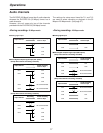
AUDIO OUT (CH1/CH2) connectors
These are the output connectors for the analog
audio signals.
9
AUDIO IN (CH1/CH2) connectors
These are the input connectors for the analog audio
signals.
:
REF VIDEO IN connectors and 75 Ω termination
switch
These are the input connectors for the reference
video signals.
Input black burst signals or composite video signals
which comply with the RS-170A standard.
Set the switch to ON for termination.
;
TC IN connector
This is the connector for recording the external time
codes on the tape.
<
TC OUT connector
During playback, the playback time code is output
to this connector. During recording, the time code
generated by the internal time code generator is
output.
=
REMOTE CONTROL connector
This unit can be operated from an external source
by connecting an optional external remote controller
(model AJ-A95P) to this connector.
<Notes>
O
Set the LOCAL/MENU/REMOTE switch to the
REMOTE position.
O
This complies with the RS-422A interface
standard but the functions associated with editing
do not work.
>
ENCODER REMOTE connector
An optional external encoder remote controller
(model AU-ER65B) is connected to this connector
when the video output signal settings are to be
adjusted from an external source.
<Note>
Set setup menu item No.00 to REMOTE.
(See page 27)